Трапециевидные наружные консоли CH 601 HDS по HDS Wings Assembly: 35 операций. Руководство помечено DRAFT, листы имеют даты 07/1996 и 09/1997, завершающая строка текста — 31.03.1998. Источник поясняет сборку, но не заменяет полный применимый комплект 6SV. Это крыло HDS; его нервюры, расстояния, подкладки и крутка элерона не переносятся в прямоугольное крыло HD или UL. Разночтения текста и рисунков отмечены у соответствующих операций.
Иллюстрации предназначены для пояснения сборки, не являются шаблонами деталей и не заменяют чертежи. При расхождении руководство отдаёт приоритет применимым чертежам. Толщины .016, .025 и .063 приведены в дюймах; остальные единицы указаны у размеров. I/B — к корню, O/B — к законцовке. Cleco — временный съёмный фиксатор.
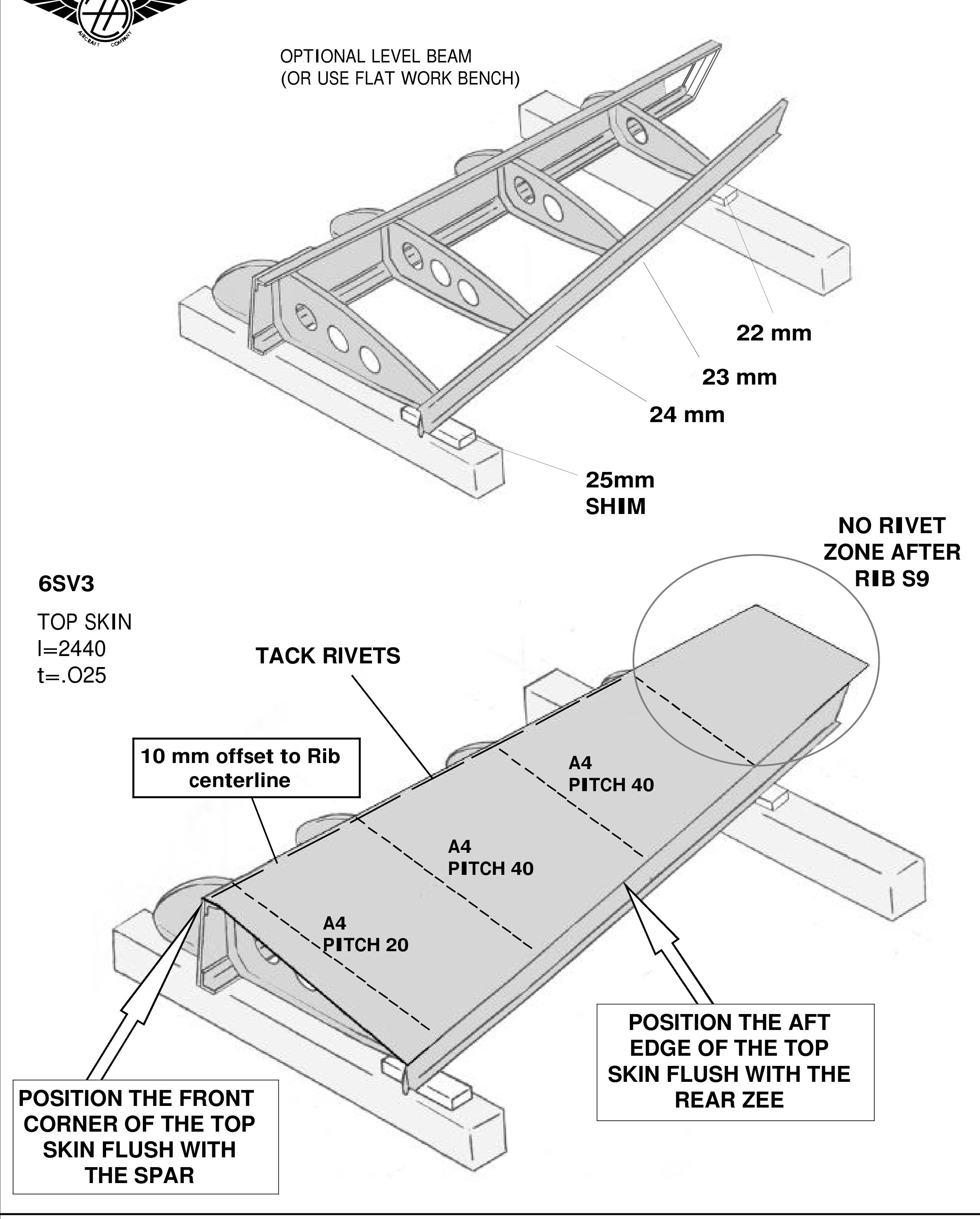
V-11: подкладки 25/24/23/22 мм, совмещение обшивки с поясом и задним профилем, технологическая прихватка и зона без клёпки за №9. Эти подкладки задают именно данную геометрию HDS.
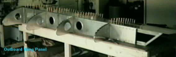
Фотографии постройки HDS
Частные проекты соответствующей модели. Отделка и приёмы автора не подменяют размеры и порядок из применимых чертежей.
Сверление и временное крепление обшивки к каркасу · Фил Полстра · Открыть крупно
Фото: Фил Полстра. Архивный источник. Это пример частной постройки, не размерный шаблон.
Шаг 11. На непросверленной полке L-профилей делают гофры для кривизны, проверяя каждый профиль по задней нервюре. Шаг 12. Верхнюю обшивку 6SV3-5 ставят на каркас; линии из готовых отверстий продолжают до передней кромки и совмещают со станциями, отмеченными на поясах в шаге 6. Прижимают к лонжерону, задний профиль совмещают с его отверстиями и рядами задних полок.
Проверяют совпадение станций с отверстиями в обшивке, видимость осей полок и положение заднего края заподлицо со стенкой Z-профиля. В строке PITCH написано «50 A4 (table on 6SV4)» без уточнения слова «шаг»; эта неоднозначная запись не переименована в новую раскладку. У нервюры №6 явно указан шаг 25 мм. Задний ряд сверлят позже при установленном элероне.
Перед сверлением заднюю часть поддерживают проставками: S6 — 25 мм, S7 — 24, S8 — 23, S9 — 22. Сверлят №30 при видимой оси полки, при необходимости корректируя нервюру снизу.
Шаг 13. Три L-усилителя между станциями ставят Cleco и подгоняют гофры по профилю крыла, работая снизу. Шаг 14. Обшивку прихватывают к лонжерону плоскими технологическими заклёпками: точка в 20 мм влево от ряда нервюры попадает в середину 40-мм шага на лонжероне. Это удерживает прямолинейность и не даёт каркасу сдвинуться при перевороте. Указаны A4 с плоским наконечником заклёпочника, соответствующим заклёпкам 1/8 дюйма.
Шаг 15. Верхнюю обшивку заклёпывают к каркасу, но ряды за нервюрой №9 пока оставляют открытыми.
Сверить с исходным текстом
REAR TOP SKIN
V-10
The pre-drilled holes in the Skins will square the Ribs to the Main Spar. Adding tack rivets along
the front edge into the extrusion will assure the spar stays straight during construction.
11. Crimp the un-drilled flange of the L angles to add curvature. For an effective crimping tool,
refer to page 4 of the Construction Manual
CHECK : Compare the curvature of the L angles by holding it up against a Rear Ribs.
12. Cleco the Rear Top Skin 6SV3-5 on the wing skeleton.
REFERENCE: 6SV3-5
LAYOUT: Mark the rib station on the front edge of the skin: use a straight edge to connect
the predrilled holes in the skin to extend the rib rivet line to the front edge of the sheet.
POSITION: Line up the rib station marks on the spar extrusion, from step 6, with the rib
station lines marked on the edge of the sheet. Clamp the Skin to the Spar. Clamp the Rear Zee
to the Skin when the pre-drilled holes for the rive line are in line with the rivets in the rear
flange of the Rear Ribs and Rear Zee from Step 3
CHECK: a) The Rib Stations in the Rear Zee line up with the pre-drilled holes in the Skin
b) The Rib Stations marked on the top of the Spar extrusion line up with the Pre-
drilled holes.
d) The Rib flange center line is visible through the pre-drilled holes, the Rib can be
moved for better alignment.
e) The aft edge of the skin is flush with the Rear Zee web.
PITCH: a) 50 A4 (table on 6SV4).
b) The pitch at rib #6 is 25mm.
TIP: Drill the rear rivet line later with the Aileron clamped in place.
DRILL & CLECO: Before drilling, support the trailing edge by placing the following
spacers underneath the Rear Ribs (see page 5 of the Speed Wing Construction Manual):
R.R. # S6 use spacer 25mm
S7
24
S8
23
S9
22
Back drill with #30 when the rib flange center line is visible. Reach under to adjust the
position of the rib to align the center line!
13. Cleco the 3 stiffener L Angles between the Rib stations.
REFERENCE: 6SV4 top right diagram, 6V8. Page 17 of the Construction Manual.
CHECK: the curvature of the Stiffeners with the wing profile. Reach in from below to make
necessary adjustments to the crimp (see page 17 of the Construction Manual).
14. TACK RIVETS (Flush tack) the skin to the spar. Position the track rivets 20mm to the left of
the rivet line through the ribs (with a rivet at the intersection of the rivet line through the rib and
spar the tack rivet is positioned in the middle of the 40mm pitch of the spar rivet line).
Reference page 11 of the Construction Manual.
NOTE: The tack rivets will keep the spar straight with the edge of the skin. The tack rivets also
prevent the skeleton from shifting when the assembly is turned over to install the bottom skin.
RIVET: A4 with a flat nose piece on the riveter head. Check the diameter of the inside hole in
the nose piece, use the appropriate nose piece for the 1/8” rivets!
15. RIVET: The Top Skin to the Skeleton, wait to rivet the rivet lines after rib #9
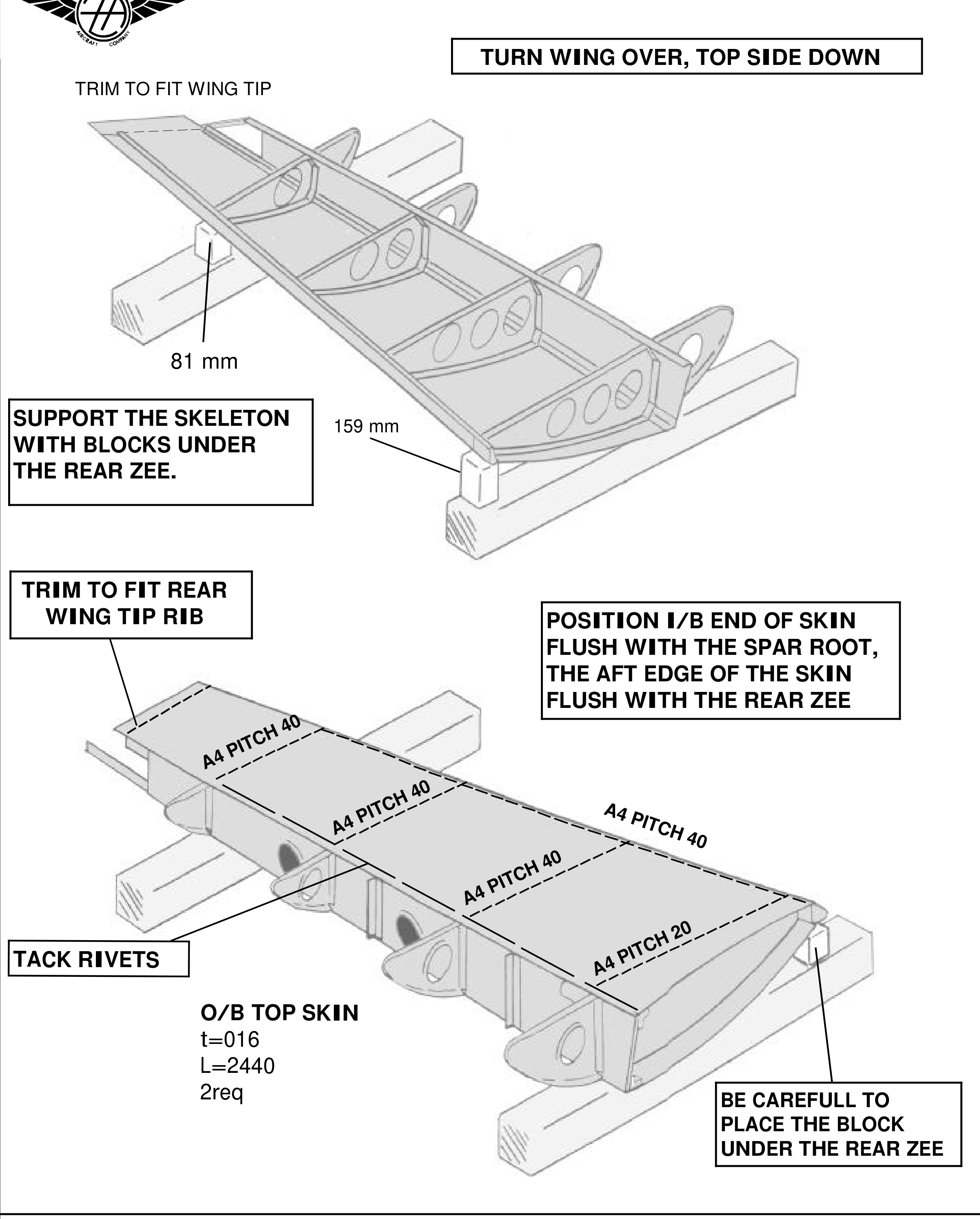
V-13: перевёрнутое крыло и подкладки 159/133/107/81 мм. Брусок ставят под задний Z-профиль, а не произвольно под тонкую обшивку. Подпись TOP SKIN на листе расходится с названием главы.
Шаг 16. Консоль переворачивают, L-профили гофрируют по нижней кривизне нервюр. Шаг 17. Нижнюю обшивку 6SV3-6 ставят с задним краем заподлицо с Z-профилем и внутренним торцом по корню главного лонжерона. Ссылки: 6SV3-6, 6SV1-2.
Под задними частями нервюр ставят проставки: S6 — 159 мм, S7 — 133, S8 — 107, S9 — 81. Формула источника: из последней координаты X вычитают верхнюю U и добавляют 2 мм под толщину верхней обшивки; пример S6: 264 − 107 + 2 = 159. Это не те же подкладки 25–22 мм, которые применялись при сборке верхней стороны.
Станции из отверстий продолжают до переднего края листа, совмещают с отметками поясов. Обшивку прижимают, проверяют среднее положение заднего ряда на полке Z-профиля, передний край по лонжерону и оси нервюр через отверстия. Текст повторяет неоднозначное «50 A4 (table on 6SV4)», а для №6 явно даёт шаг 25 мм.
Шаг 18. L-профили подгоняют и устанавливают. Шаг 19. Передний край обшивки прихватывают к поясу. Шаг 20. Снимают заусенцы, собирают Cleco и заклёпывают. На V-13 лист в заголовке детали назван O/B TOP SKIN при толщине .016, хотя текст относится к нижней обшивке 6SV3-6. Подпись не переименована в указание ставить верхнюю .025 вместо нижней.
Сверить с исходным текстом
REAR BOTTOM SKIN
V-12
Turn the wing over, and support the trailing edge.
16. Crimp the L angles using the bottom curvature of the ribs as a guide.
17. Position the Bottom Skin 6SV3-6.
REFERENCE: 6SV3-6, 6SV1-2
SUPPORT: Support the Ribs at the rear using the following block spacers:
S6 159
S7 133
S8 107
S9 81
Subtract upper coordinate U from the last station X from station 0 add 2mm for the
thickness of the top skin as shown drawing 6SV1 . Example for S6: 264 –107 + 2 = 159
POSITION: a) The aft edge flush with the Zee.
b) The I/B end is flush with the Root of the Main Spar.
LAYOUT: Mark the rib station on the front edge of the skin: use a straight edge to connect the
predrilled holes in the skin to extend the rib rivet line to the front edge of the
sheet.
POSITION: Line up the rib station marks on the spar extrusion, from step 6, with the rib
station lines marked on the edge of the sheet. Clamp the skin to the Spar. Clamp
the Rear Zee to the Skin when the pre-drilled holes for the rive line are in line with
the rivets in the rear flange of the Rear Ribs and Rear Zee from Step 3
CHECK: a) The pre-drilled holes in the Skin for the aft rivet line for the Rear Zee are in the
middle of the flange.
b) The front edge of the skin is flush with the spar.
b) The pre-drilled holes for the rib rivet line are in line with the rib.
PITCH: a) 50 A4 (table on 6SV4).
b) The pitch at rib #6 is 25mm.
18. L ANGLES: Crimp and Install the L Angles
19. TACK RIVETS the front edge of the skin to the spar.
20. CLECO & RIVET: De-burrs.
Страница 15 исходного PDF
Носовая обшивка и контроль геометрии
Носовая обшивка и контроль геометрии · лист 16 · Открыть крупно
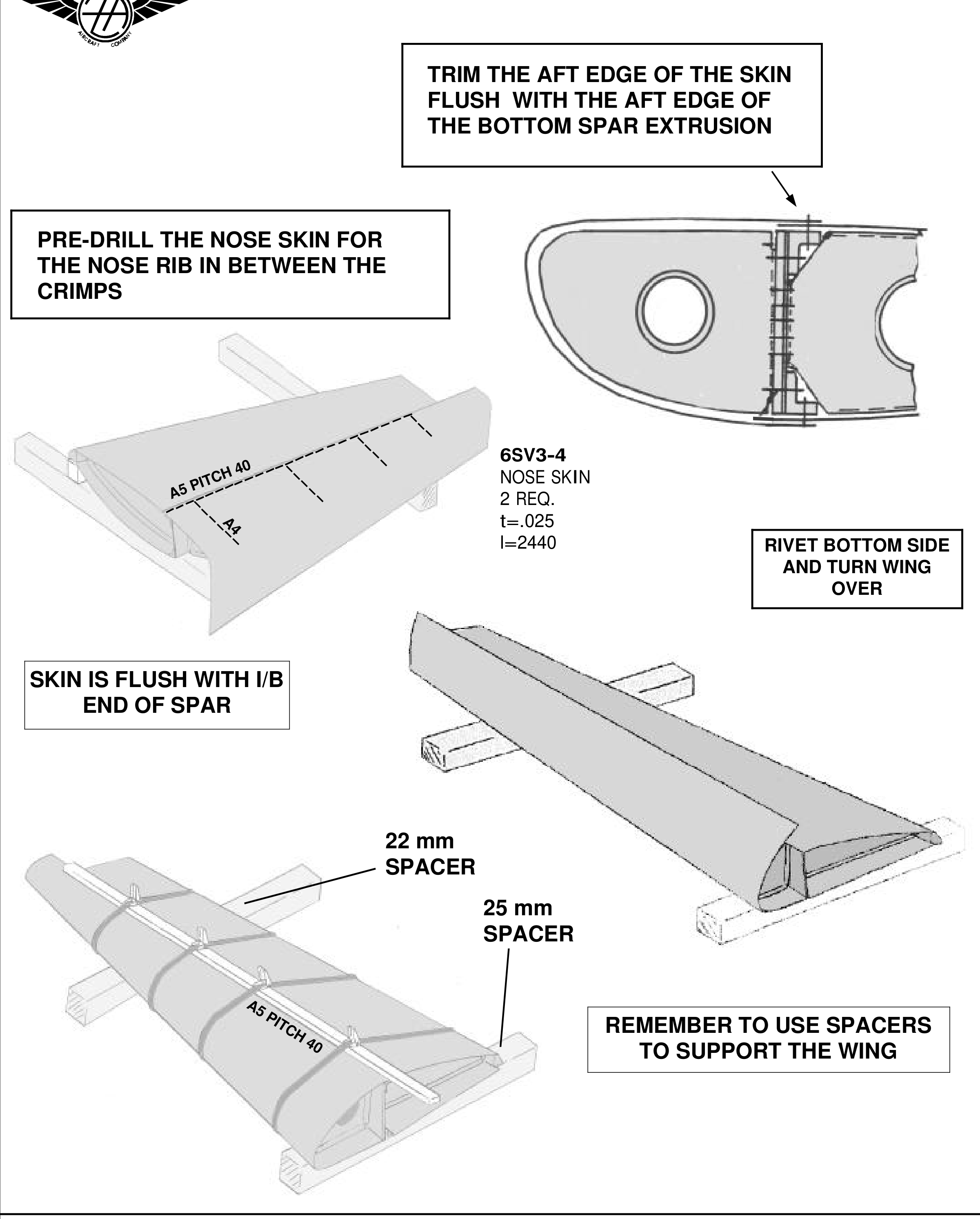
V-15: сначала низ носовой обшивки, затем переворот; подкладки 22/25 мм и сверление между гофрами. Разночтение внутреннего выпуска указано в тексте.
Шаг 21. Сначала крепят нижнюю сторону носовой обшивки 6SV3-4 при перевёрнутой консоли. На листе длиной 8 футов отмечают ось радиуса: текст даёт 411 мм при dl=947 у корня и 232 мм при dl=232 на конце, соединяя прямой. Повтор 232 как координаты и dl выглядит разночтением самого исходника; развёртку по нему не вычисляют без применимого 6SV3-4.
На каждой нервюре большим угольником от её плоского низа находят касание носка — отметку FRONT; от неё по нижней кривизне откладывают 40 мм. Заднюю часть крыла поддерживают подкладками шага 17. Внутренний край носовой обшивки в тексте выпускают на 20 мм за низ корня лонжерона, задний край совмещают с задней кромкой пояса. Линия 40 мм на нервюрах должна совпадать с осью гиба обшивки.
Ряды продолжают с задних нервюр, обшивку снимают для раскладки. Первое отверстие на полке — в 10 мм от конца; максимальный шаг 40 мм, промежутки при необходимости делят дополнительной заклёпкой для обхода гофр. Раскладку с каждой нервюры на обшивку переносят отдельной полосой от общей задней базы пояса. Пилотные №40; при окончательном сверлении должна быть видна ось полки.
Шаг 22. Консоль переворачивают. Длинным бруском 2 × 4 дюйма, 8 футов, носовую обшивку опускают на нервюры; ремни идут по бруску и под столом. На нижнюю полку заднего Z-профиля ставят защитный брусок 2 × 4, чтобы ремень не смял её; ремень — у каждой нервюры. Задние ряды продолжают на носовую обшивку, отмечают перекрытие, ремни снимают для разметки и пилотного сверления, затем ставят снова для сверления по осям.
Если стол не выровнен, под крыло у №6 и №9 кладут две параллельные балки поперёк лонжерона, выравнивают их и ставят между балкой и задним профилем проставки 25 и 22 мм. При опоре на головки заклёпок источник добавляет 2 мм. Разность высот у №6 и №9 должна быть 3 мм. На V-15 носовая обшивка .025 дюйма, длина 2440; показаны отдельные ряды A5 с шагом 40 и A4. Надпись на рисунке о положении внутреннего края заподлицо отличается от выпуска 20 мм в тексте: базу проверяют по своему листу, а не молча объединяют.
Сверить с исходным текстом
LEADING EDGE NOSE SKIN
V-14
With the wing upside down on the workbench rivet the bottom side of the Nose Skin. Turn the
wing over to strap down the top side of the Nose Skin.
21. The bottom side of the Leading Edge is riveted first.
REFERENCE: 6SV3-4
LAYOUT: a) Mark the center line of the Leading Edge radius. For 8feet skins cut to fit with
the edge flush with the aft edge of the spar, the center is at 411mm (dl=947) and
at 232mm at the tip (dl=232) connect with a straight line.
b) Mark the FRONT of each Nose Rib by holding a large carpenter square on the
flat bottom of the Rib to mark the tangent point as the FRONT of the Nose
Rib.
c) From the FRONT mark on the Nose Rib make another mark at 40mm along
the bottom curvature of the Nose Rib.
SUPPORT: With the wing upside down, support the trailing edge with the spacer in Step 17
CLAMP: a) Let the Nose Skin overhangs the bottom I/B end of the Main spar by 20mm.
b) Clamp the aft edge of the skin even with the rear of the Spar Extrusion.
CHECK: The 40mm line on the Nose Ribs lines up with the Leading Edge center line.
PRE-DRILL: a) Extend the rive line of the Rear Ribs to the Nose Skin.
b) Remove the Skin to mark the rivet pitch, approximately 40mm
SUGGESTION: Layout the rivet pitch directly on the rib flange, the first hole is at 10mm from
the end of the rib; the maximum distance between rivets is 40mm: if necessary add an extra rivet
to adjust for even rivet spacing to avoid the crimps. Clamp a strip even with the rear of the
spar extrusion, transfer the rivet spacing from the rib to the strip. Remove and clamp the strip
flush with the aft edge of the skin to transfer the rivet spacing to the skin. Repeat for each rib.
Pre-drill the skin with #40 pilot holes.
CLAMP & BACK DRILL: Clamp the pre-drill bottom side to the Spar. Adjust the position of
the Nose Rib to line up the flange center line with the pre-drilled holes.
22. Strap the Nose Skin over the Ribs.
STRAP: Use an 8 ft. 2×4 to push the Skin down on the Ribs, place the straps directly overtop
the 2×4 and underneath the workbench to keep the wing from moving. Before tightening the
strops, slide a 2×4 block on Rear Zee bottom flange to keep the strap clear of the Rear Zee
bottom flange. Position one strap by each Rib.
LAYOUT & PRE-DRILL: Extend the Rear Rib rivet line to the Nose Skin. Mark the aft edge
of the Nose Skin on the Rear Skin to reference the rivet pitch template. Remove the straps to
layout the rivet pitch on the Nose Skin. Pre-drill with pilot holes.
DRILL & CLECO: Strap down the Nose Skin, add the spacer underneath the Rear Zee and
drill the Ribs when the flange center line is visible.
COMMENT: If the work bench is not level, slide two parallel beams underneath the wing
assembly at Rib #6 and #9 (perpendicular to the Main spar). Level the beams and add the 22
and 25mm spacers between the beam and the Rear Zee. If the wing is resting on the rivets, add
2mm to spacer to compensate for the rivet head.
SUGGESTOIN: Run the strap underneath the table and over the wing to secure the wing to
the workbench.
CHECK: The difference in the height of the spacers at the Rear Zee between Rib #9 Rib #6 is
3mm.
Страница 17 исходного PDF
Швартовочное кольцо и законцовка
Швартовочное кольцо и законцовка · лист 18 · Открыть крупно
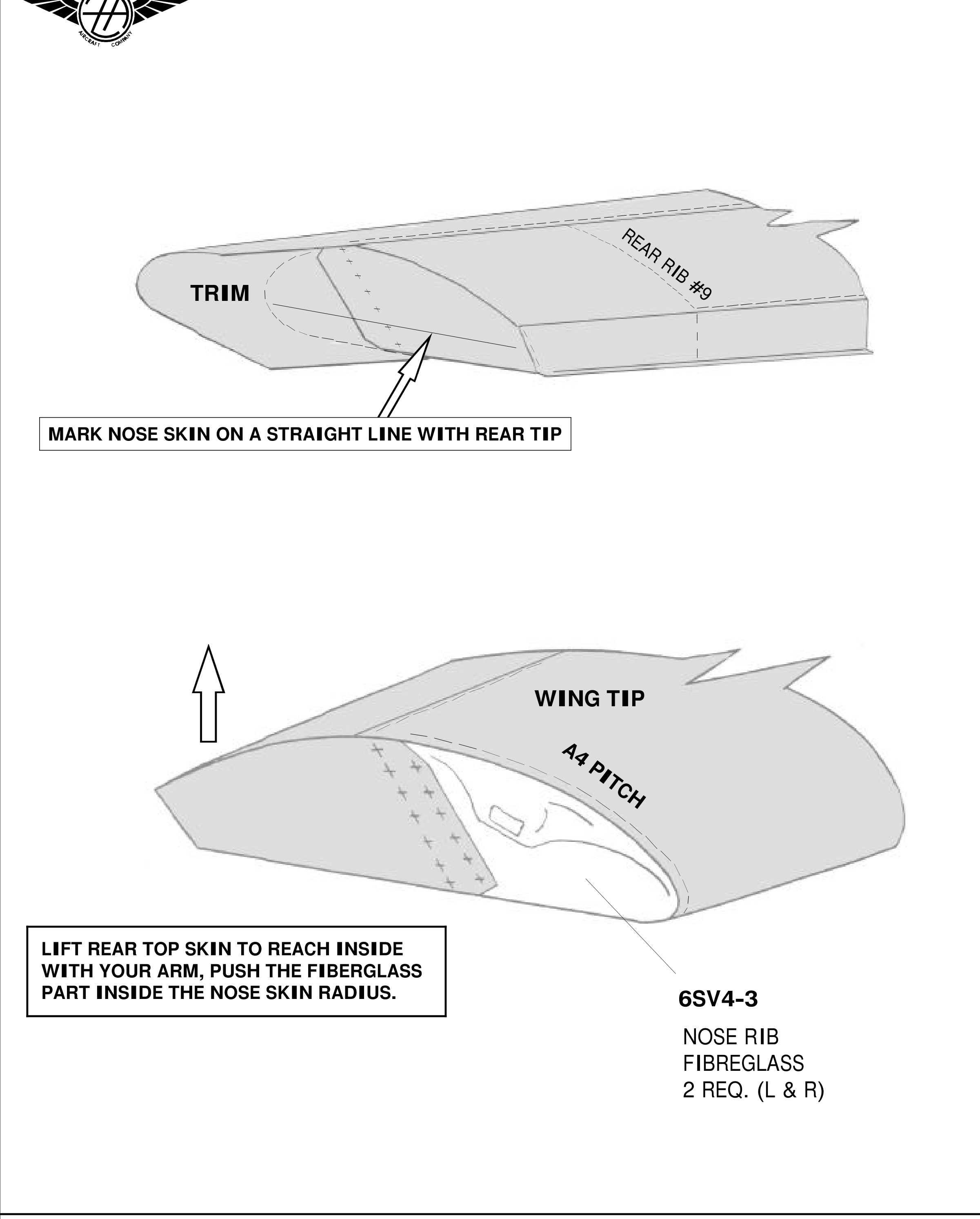
V-17: стеклопластиковая 6SV4-3, доступ через задний угол верхней обшивки и единая линия с задней законцовкой. Полного численного шага в подписи «A4 PITCH» на этом рисунке нет; число не придумано.
Носовую обшивку подрезают под тот же угол 45°, что и концевую заднюю нервюру: прямую рейку кладут на нервюру и маркером на её конце переносят линию на носовую обшивку.
Шаг 23. Кольцо швартовки 6V3-1 ставят через нижний пояс главного лонжерона в 40 мм внутрь от крайней наружной нервюры по сечению AA на 6V3.
Шаг 24. По концевой задней нервюре 6SV3-2 обводят верхнюю и нижнюю задние обшивки и подрезают по контуру. Заклёпки в концевую нервюру пока не ставят до примерки стеклопластиковой законцовки 6SV4-3.
Шаг 25. Носовую обшивку подрезают под установку 6SV4-3. Руководство описывает разные направления перекрытия стеклопластика и концевой нервюры; один вариант может дать более прямую законцовку. Эта фраза не заменяет проверку применимого соединения и не задаёт нового универсального нахлёста.
Внутреннее перекрытие проверяют, приподняв задний угол верхней обшивки. Для навигационного/проблескового огня плоскую площадку располагают под 90° к главному лонжерону, как показано в этом руководстве. Стеклопластик предлагается подрезать ручными ножницами. Для первых отверстий концевую нервюру снимают либо через открытый угол верхней обшивки плотно прижимают стеклопластик к радиусу носовой обшивки и ставят Cleco.
Сверить с исходным текстом
WING TIP
V-16
Trim the Nose Skin on the same 45 degrees angle as the Rear Tip Rib: tape a marker at the end of a
yard stick, lay the yard stick flat on the Tip Rib to trace the Nose Skin.
23. Install the Tie Down Ring 6V3-1 are positioned through the Lower Spar Cap Angle (extrusion)
at 40mm inboard of the most outboard rib as shown on drawing 6V3 section AA (top right
diagram and bottom right detail).
24. Trace around the Rear Tip Rib 6SV3-2 to mark the Top Rear and Bottom Rear Skins.
TRIM: Trim the Rear Skins to mach the Rear Tip Rib.
RIVET PITCH:
DRILL & CLECO: Wait to rivet the Skins to the Rear Tip Rib 6SV3-2 until the Fiberglass
Nose Rib 6SV4-3 is installed.
25. Cut the Leading Edge Skin to install the Fiberglass Wing Tip 6SV4-3
COMMENT: Some builders prefer to overlap the Fiberglass over the Rear Tip Rib to avoid
the reverse overlap as shown on V-9 . How the overlap is made is insignificant, overlapping
the Tip Rib over the Fiberglass tip may make a straighter tip!
TIP: Look inside the wing by lifting the rear corner of the Top Skin to check the overlap of the
Nose Skin over the Fiberglass Tip.
Nav/Strobe system: Install the Fiberglass Tip with the flat portion for mounting the lights at
90degrees to the Main Spar for correct light distribution required for night flying.
SUGGESTION: Use the hand snips to cut the Fiberglass Tip.
RIVET LINE:
HINT: Remove the Rear Tip Rib or reach in by lifting the Top Skin to firmly push the
Fiberglass Tip inside the radius of the Nose Skin to drill and Cleco the first few holes.