Перевод 16 операций elevator.pdf, печать 24.10.2001; рисунки имеют редакции 07/1996 и 03/2000. Это описанная в источнике конструкция семейства, сопоставленная с веткой CH 601 HD. Поздняя сводка HD 09/2003 меняет геометрию нижнего кабанчика и длину усилителя, а 08/2004 уточняет изображения. Старый порядок сборки не объявлен актуальным размерным комплектом. Ведомость на T-15 имеет неполную строку количества нервюр, тогда как T-18 указывает 3L & 3R; число не берут по одной неполной строке.
Руководство обозначено как DRAFT: оно поясняет сборку, но не заменяет применимые чертежи и не является шаблоном изготовления. Файлы найдены в исторической коллекции HDS, но эти конкретные руководства относятся к семейству CH601; материал HD сверяется отдельно, без переноса HDS-крыла или UL-толщин.
Нервюры, центральный профиль и разметка · исходный лист 5 · Открыть крупно
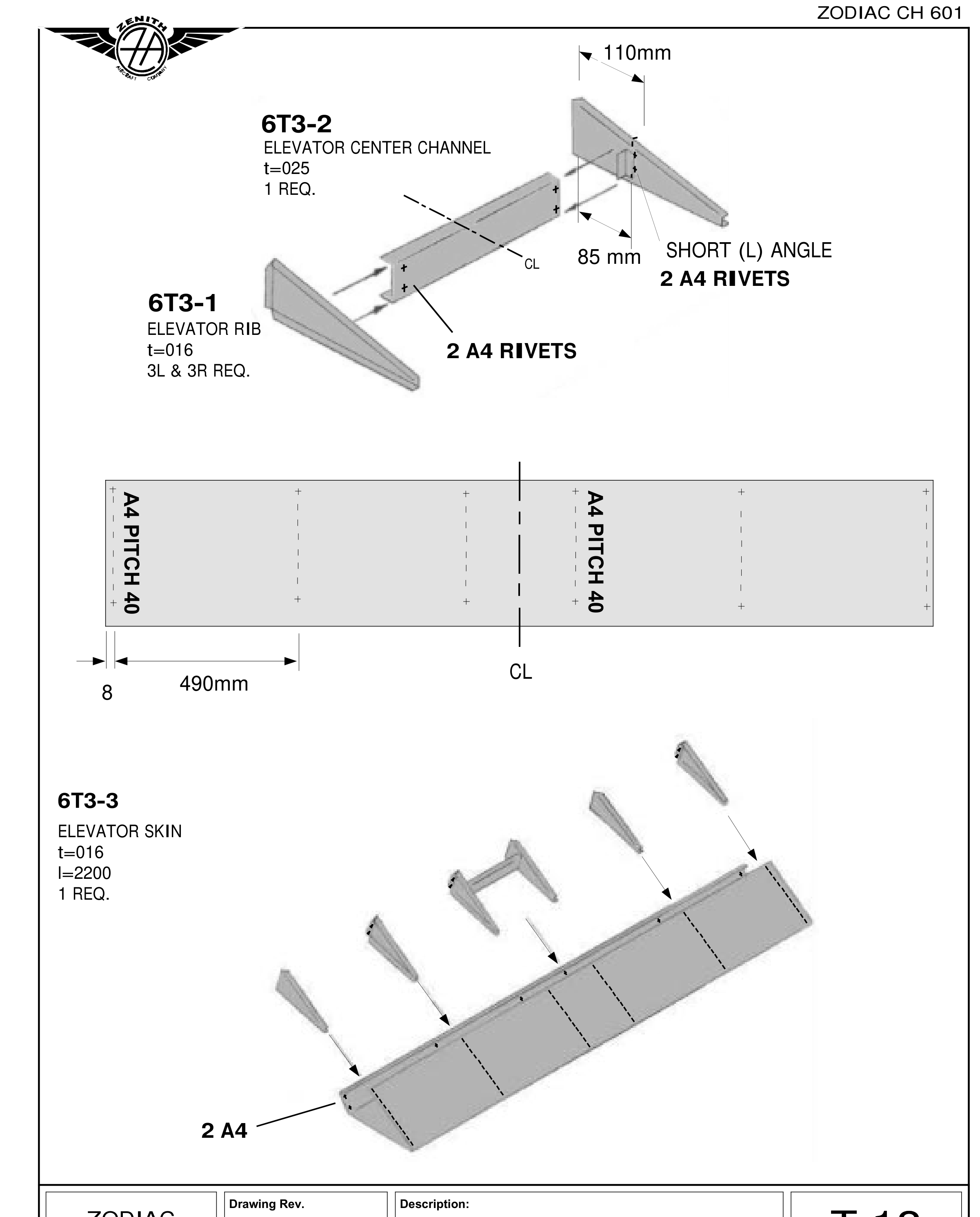
T-18: центральная пара нервюр с 6T3-2, базы 110/85 мм, концевой ряд 8 мм и промежуточная станция 490 мм. Показаны по два A4 в уголках и рядах соответствующих соединений.
Шаг 1. К одной левой и одной правой нервюре 6T3-1 временно ставят короткие L-профили. Базовый прямой край, например 6T3-6, прижимают к передней полке. От него по верху отмечают 110 мм, по низу 85 мм, точки соединяют. L-профиль ставят позади линии, которая задаёт его передний край.
Стандартный L-профиль этой редакции: 6061-T6, .025 дюйма, гиб 90°, полки 18 × 18 мм, поставляемая длина 4 фута. Отрезают две заготовки примерно по 90 мм. Первое отверстие — примерно в 10 мм от верха нервюры, второе в 10 мм от нижней полки; всего два отверстия №30 через полку и нервюру. После Cleco верх и низ обводят, профиль снимают и подрезают по ширине нервюры. Нужна одна левая и одна правая сборка.
Шаг 2. Центральный профиль 6T3-2 прижимают к коротким L-профилям по центру между верхней и нижней полками нервюр. Сверлят и ставят Cleco по два отверстия под A4 на соединение профиля с уголком, затем заклёпывают уголки к нервюрам и профилю.
Шаг 3. На обшивке 6T3-3 размечают оси полок как ряды заклёпок. Ряд концевой нервюры — в 8 мм от торца; от него по переднему краю откладывают 490 мм для следующей нервюры. Большим угольником продолжают линии перпендикулярно задней кромке. Две центральные нервюры размечают по фактической сборке с профилем, центрированной по оси самолёта; оси полок находят между их краями. Нервюры также под 90° к задней кромке. На T-18 нервюры и обшивка .016 дюйма, профиль .025, обшивка длиной 2200.
Сверить с исходным текстом
ZENITH AIRCRAFT COMPANY
Print Date: 10/24/01
ZODIAC CH 601
ELEVATOR RIBS T-17
The Elevator Center Channel attaches to the two middle Elevator Ribs with a short length of L
Angle. First Cleco the L Angle to the Rib then cut the length of the Angle to match the width of
the Rib. The Channel is Clecoed on the front side of the L Angle with 2 #30 Clecos in each
Angle.
Layout the rib station along the front side of the Elevator Skin, then with a large carpenter
square extend the rib center line to the trailing edge.
1. Cleco the Short L Angle to the side of one left and one right Elevator Rib 6T3-1
LAYOUT Clamp a reference edge (or a piece of extrusion such as 6T3-6) on the front
flange of an Elevator Rib 6T3-1. Lay a thin ruler on the top flange of the Rib zeroed at the
reference edge to layout a mark at 110mm . Along the bottom flange layout a mark at 85mm
from the reference line. Connect the 110 and 85 marks with a straight line on the side of the
Rib. The L Angle is positioned behind the line (the line marks the front of the L Angle).
STANDARD L ANGLE: 6061-T6 alloy thickness .025 bent at 90 degree, flanges 18mm x
18mm. Supplied length of 4 feet. Cut 2 pieces approximately 90mm long, they will be cut to
the exact length after they are Clecoed to the Rib.
DRILL/CLECO: Position the L Angle on the side of the Rib with the front edge on the
line. Drill the first end hole at approximately 10mm from the top of the Rib and Cleco. The
second hole is at 10mm from the bottom flange of the Rib. Total of 2 #30 in the flange and
Rib.
TRIM: Cut the length of the L Angle the same width as the Rib, with a marker trace the top
and bottom rib flange on the L Angle, remove L Angle from the Rib and trim with the snips.
QUANTITY: 1 left and 1 right Rib.
2. Rivet the Elevator Center Channel 6T3-2 to the two short L Angles .
CLAMP: Clamp the Channel to the Short L Angle centered between the top and bottom rib
flange.
DRILL/CLECO: Drill and Cleco the first end hole. Total of 2 A4 in the Channel and Short
L Angle.
RIVET: Rivet the Short L Angles to the Ribs and to the Channel.
3. Layout the Rib stations on the Elevator Skin 6T3-3 (the flange center line is the rivet line).
End Ribs: The rivet line for the end ribs is in 8mm from the end of the Skin.
Middle Ribs: From the rivet line of the end Ribs layout a mark at 490mm along the front
edge of the Skin. Use a large carpenter square to extend the rivet line perpendicular with the
trailing edge.
Center Ribs: To trace the separation of the two center Ribs position the Rib and Channel
assembly on top of the Skin: align the assembly on the aircraft center line. Locate the rib
center line as the middle of the flange (trace both sides of the flange and split in half) The Rib
is also 90 degrees to the trailing edge.
PITCH: Continue on next page T-19 step #4
Страница 6 исходного PDF
Сверление обшивки и вырезы под усилитель
Сверление обшивки и вырезы под усилитель · исходный лист 7 · Открыть крупно
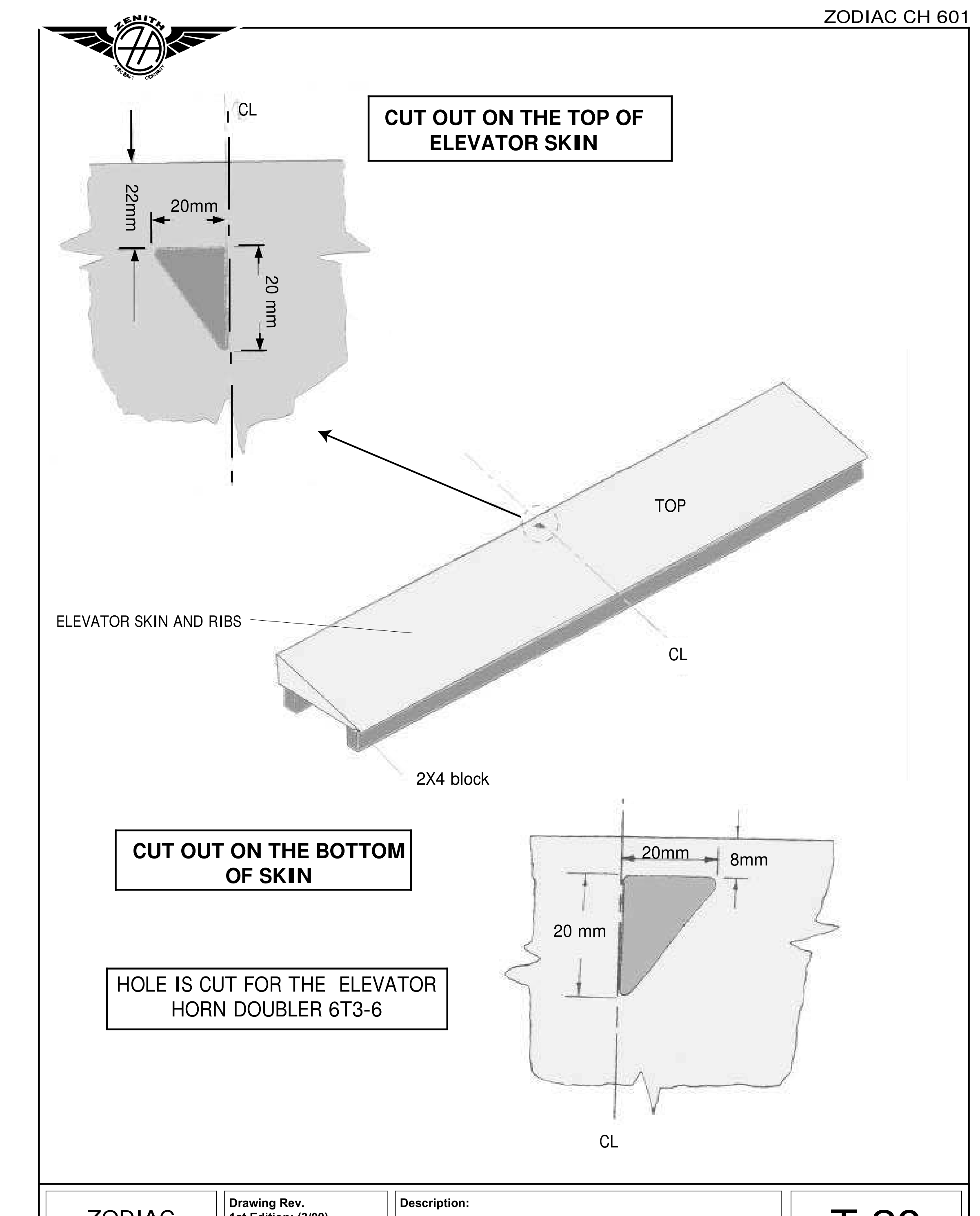
T-20: отдельные верхний и нижний вырезы слева от оси. Верхняя база 22 мм, нижняя 8 мм; полки прорези по 20 мм. Это не симметричный вырез относительно оси самолёта.
Шаг 4. На полках нервюр раскладывают шаг между крайними отверстиями, расположенными в 10 мм от концов полок. Пересечение рядов с профилем 6T3-2 также считается крайним отверстием; крайние отверстия самого профиля — в 10 мм от его концов. Между крайними отверстиями раскладывают шаг 40 мм: в этой редакции получается девять отверстий сверху, восемь снизу, а в передней полке только два крайних. Точный ряд центрального профиля пока ждёт установки кабанчиков и L-профилей.
Отверстия пересечений верхнего ряда с рояльной петлёй пока не сверлят: временные отметки крайних отверстий служат лишь раскладке шага. Станции в трёх полках предварительно сверлят №40, на каждой полке отмечают середину. Обшивка лежит на столе верхом вверх; первыми сверлят к ней два отверстия передней полки, удерживая осевую линию видимой в пилотных отверстиях. При сверлении №30 полку поддерживают небольшим бруском 1 × 2 дюйма. Затем сборку переворачивают: нижние полки сверлят от переда к задней кромке, №30 с Cleco сначала через каждое третье отверстие, затем промежуточные.
Шаг 5. Усилитель кабанчиков 6T3-6 проходит через верх и низ слева от оси самолёта, если смотреть из кресла пилота. При разметке верха работают лицом к задней кромке; для низа сборку поворачивают на 180° вокруг задней кромки — левая сторона остаётся той же стороной оси.
Вместо треугольного проёма T-20 предложена L-образная прорезь по сечению уголка. Для треугольного выреза сначала выполняют три разгрузочных отверстия 1/4 дюйма. Подробный текст далее описывает вариант с одним угловым отверстием и круглым напильником. Снизу линию откладывают примерно на 8 мм назад от переднего радиуса гиба; бок усилителя совмещают с осью, его угол — с пересечением линий, сечение обводят. Продолжение верхнего выреза приведено в следующей группе.
Сверить с исходным текстом
ZENITH AIRCRAFT COMPANY
Print Date: 10/24/01
ZODIAC CH 601
ELEVATOR HORN DOUBLER T-19
The Elevator Horn Doubler is installed through the Elevator Skin to connect the Upper Elevator
Horn to the Lower Elevator Horn. The cutout in the top and bottom side of the Elevator Skin is to
insert the Doubler through the Elevator.
4. Layout the rivet pitch between the end holes along each flange, then pre-drill with pilot holes.
Start positioning the Ribs inside the Skin; the Skin is flat on the workbench top side up
position. Back drill and Cleco through the front flange first, then turn the assembly over to
back drill and Cleco the bottom flange.
END HOLES: Layout the end holes along the rivet line 10mm in from the end of the Rib
Flange.
INTERSECTION HOLES: Treat the intersection of rivet lines as an end hole. Locate the
rivet line through the top and bottom flange of the Channel 6T3-2, extend the center line to
intersect with the Rib station. The end holes in the Channel are also located at 10mm from
the ends of the channel.
PITCH: Divide the distance in between the end holes for pitch 40 On the top flange this
works out to 9 holes. The bottom flange has 8 holes In the front flange there are just the 2
end holes. Wait to set the rivet pitch for the Channel 6T3-2 until after the Horn and L Angle
have been positioned.
DRILL PILOT HOLES: Wait to drill intersection holes of the rib station with the center
line of the piano hinge, even better is to erase the upper front end hole in the top flange of
the Ribs (the end holes were located to set the rivet pitch). Pre-drill the rib stations with #40
pilot holes in the three flanges.
FLANGE CENTER LINE: : Mark the Rib flange center lines on each rib.
BACK-DRILL the FRONT FLANGE: Start with the two holes in the front flange of the
Ribs. Adjust the Rib position inside the Skin until the flange center line is visible through the
pilot holes – for added support hold a small piece of 1×2” wood strip against the front Rib
flange when drilling the #30 hole.
BACK-DRILL the BOTTOM FLANGE: Work with the Skin flat on the workbench, start
at the front and drill towards the trailing edge. #30 holes, drill and Cleco every third hole,
then go back and drill the remaining holes.
5. The Cutout for the Elevator Horn Doubler 6T3-6 is located on the left side of the aircraft
center line as viewed from the pilot seat. To mark the cutout on the top side work facing the
trailing edge of the Elevator. To mark the bottom side, rotate the assembly about the trailing
edge 180degrees, the left is still on the same side of the centerline!
SUGGESTION: An alternative opening to the triangular holes shown on page T-20 is an L
shaped slot the width of the extrusion – drill 3 corner relief holes and use a chain saw file to
join them.
COMMENT: To snip the triangular cutout first drill the three ¼” relief holes. The following
description is for the slot using one corner relief hole and a round file.
LAYOUT for the CUTOUT in the BOTTOM SIDE of the Skin: Mark an offset line
approximately 8mm back from the front bend radius of the Skin to intersect with the aircraft
center line. Hold the corner of the Doubler on the intersection point of the two lines (the
side of the Doubler is on the aircraft center line) and use a marker to trace around the end of
the Doubler marking the profile of the extrusion on the Skin.
Страница 8 исходного PDF
Верхний вырез и установка рояльной петли
Верхний вырез и установка рояльной петли · исходный лист 9 · Открыть крупно
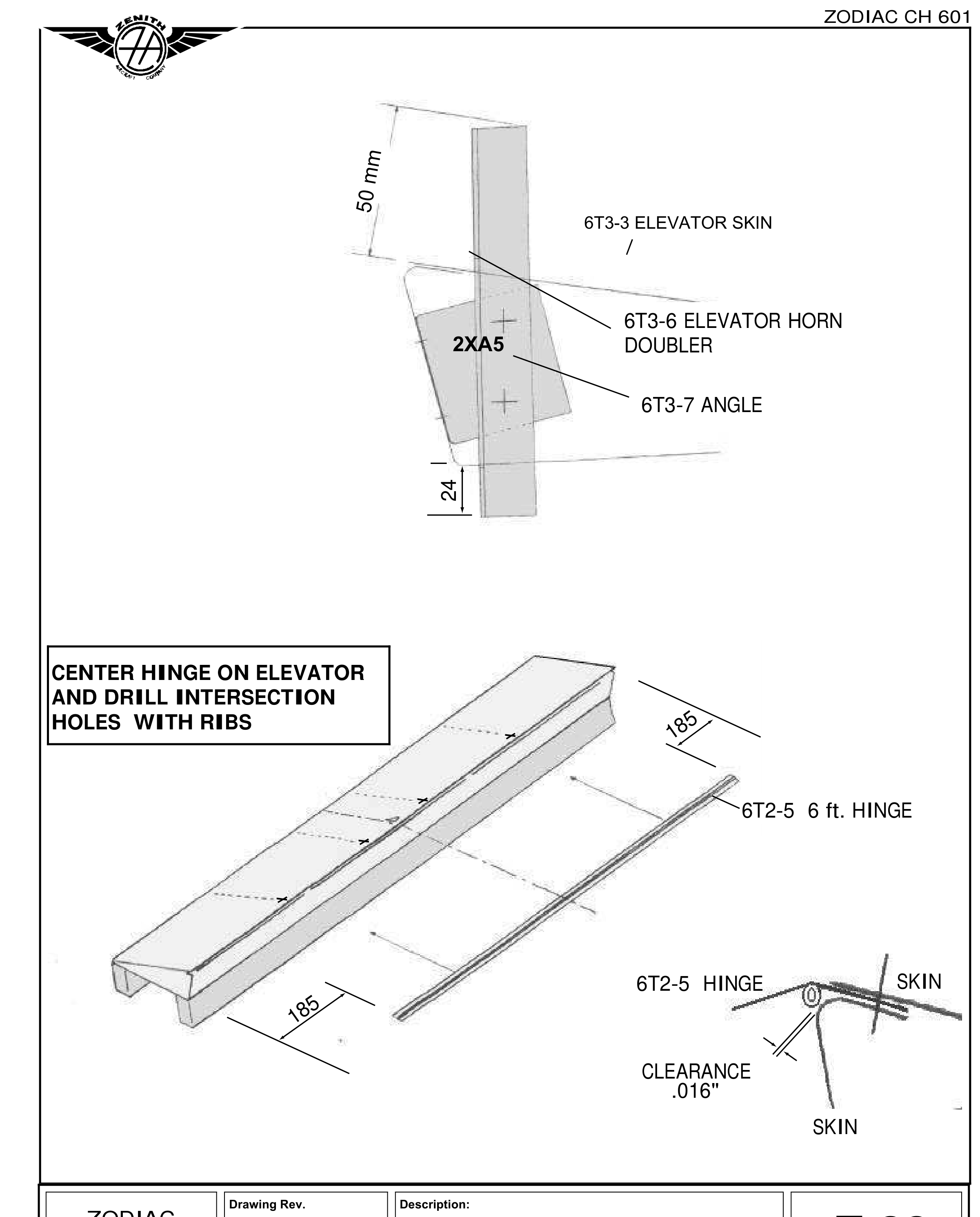
T-22: положение петли 6T2-5, расстояния по 185 мм до торцов и зазор .016 дюйма. На увеличенном виде видно, как передняя полка обшивки перекрывает полку петли.
Продолжение шага 5. Сверху проводят линию в 22 мм от переднего гиба, позади заднего края верхней передней полки. Бок усилителя 6T3-6 лежит на оси самолёта, передний угол — в пересечении. Оба выреза проверяют слева от оси. Пилотное угловое отверстие расширяют до 1/4 дюйма так, чтобы край чуть заходил за ось и поперечную линию. Круглым напильником 7/32 дюйма от отверстия делают две прорези по 20 мм: по оси и по своей линии 8/22 мм. Усилитель должен входить с небольшим свободным зазором.
Шаг 6. Сборку кладут верхом вверх на выровненные бруски 2 × 4 дюйма, освобождая Cleco над столом и исключая крутку. Источник предлагает короткие бруски вдоль нервюр, хотя T-22 показывает их в другой ориентации; каждый выравнивают подкладками, сверху можно положить распределяющий вес длинный брусок.
Петля 6T2-5 длиной 6 футов центрируется по оси, её концы примерно в 185 мм от концов обшивки. Полка петли лежит над передней полкой руля и под верхней обшивкой, штырь направлен вниз. Между кулаками петли и радиусом гиба обшивки оставляют .016 дюйма, проверяя полоской такой толщины. Передняя кромка обшивки доходит до прямого участка между кулаками. Пока верхние полки нервюр не просверлены, это положение ещё можно подогнать.
Ряд размечают посредине перекрытия петли с обшивкой, отмечают концевые и пересечения с нервюрами, промежутки делят под шаг 40 мм. Сверлят №30 и Cleco сначала через каждое третье отверстие, затем остальные; верхние полки нервюр также сверлят №30. На T-22 дополнительно подписаны 50 мм сверху, 24 мм снизу и 2 × A5 у центрального узла. Это размеры рисунка своей редакции; последующие HD-поправки к кабанчикам отмечены далее.
Сверить с исходным текстом
ZENITH AIRCRAFT COMPANY
Print Date: 10/24/01
ZODIAC CH 601
PIANO HINGE
T-21
Work with the Elevator assembly raised on 2×4”s to clear the Clecos off the workbench..
The level 2×4” beams will also assure a straight and twist free Elevator.
The edge distance of the front rivet line through the Elevator flange is set in the middle of the
Piano Hinge flange. The Piano Hinge is installed with the pin down, maintaining a .016”
clearance between the hinge hooks and the bend radius of the top flange of the Elevator Skin.
The developed length of the Elevator Skin allows the front edge of the skin to meet flush with
the straight section in between the hinge hooks. To allow for some variation, Cleco the front
rivet line through the Piano Hinge before back drilling the top flange of the Ribs to the Skin.
— continued from previous page:
LAYOUT for CUTOUT in the TOP SIDE of the Skin: Mark an offset line at 22mm from the
front bend, check to make sure the line is drawn behind the aft edge of the top flange of the
Elevator Skin! Position the side of the Doubler on the aircraft center line and the front corner of
the Doubler on the intersection of the two lines. Also trace around the Doubler (extrusion) on
the Skin.
CHECK: The cutout are both on the left side of the aircraft center line.
CORNER RELIEF HOLE: First drill a pilot hole in the Skin at the inside corner, then trace
around the Doubler (inside corner of the extrusion profile as traced on the Skin). Open the pilot
hole with a ¼” diameter hole, the edge of the hole extends just beyond the aircraft center line and
the offset line.
FILE: Use a round rat tail file (7/32” chain saw file) starting at the ¼” relief hole to “saw” two
slots 20mm long: one along the edge of the aircraft center line and the other along the 8mm and
22mm offset line. File until the Doubler fits loosely in the slot.
6.
Position the Piano Hinge 6T2-5. Turn the Elevator Assembly right side up. To get the
Clecos off the workbench, support the assembly on 2×4” boards.
SUGGESTION: Use small 2×4”sections positioned parallel to the Ribs (at 90 degrees to
what is shown on T-22. With a water level shim each 2×4 board as required, then position
the Elevator assembly on top of the level boards. Lay a heavy 2×4 board the span of the
Elevator to help weight it down.
Top rivet line: The Piano hinge 6T2-5 fits on top of the Elevator flange and is covered by
the top side of the Elevator Skin. Center the 6 ft. length of Piano Hinge on the aircraft center
line: the ends of the hinge are approximately 185mm in from the ends of the Skin. Use a
piece of .016” sheet to set the clearance between the hinge hook (part of the piano hinge that
holds the pin) and bend radius Elevator Skin. Check that the front edge of the skin overlaps
flush with the straight section between the hinge hooks, if necessary bring the two together –
the assembly is still quite flexible without the top flange of the Ribs drilled to the Skin.
Mark the rivet line at the middle of the overlap with the skin, locate end holes and
intersection holes with the ribs, and divide the in between distance for a pitch of 40. Drill
and Cleco every third hole with #30. Finish by drilling the holes in between the Clecos.
Rib top flange: Drill and Cleco the Rib top flange with #30
Страница 10 исходного PDF
Подгонка усилителя и внутреннего уголка
Подгонка усилителя и внутреннего уголка · исходный лист 11 · Открыть крупно
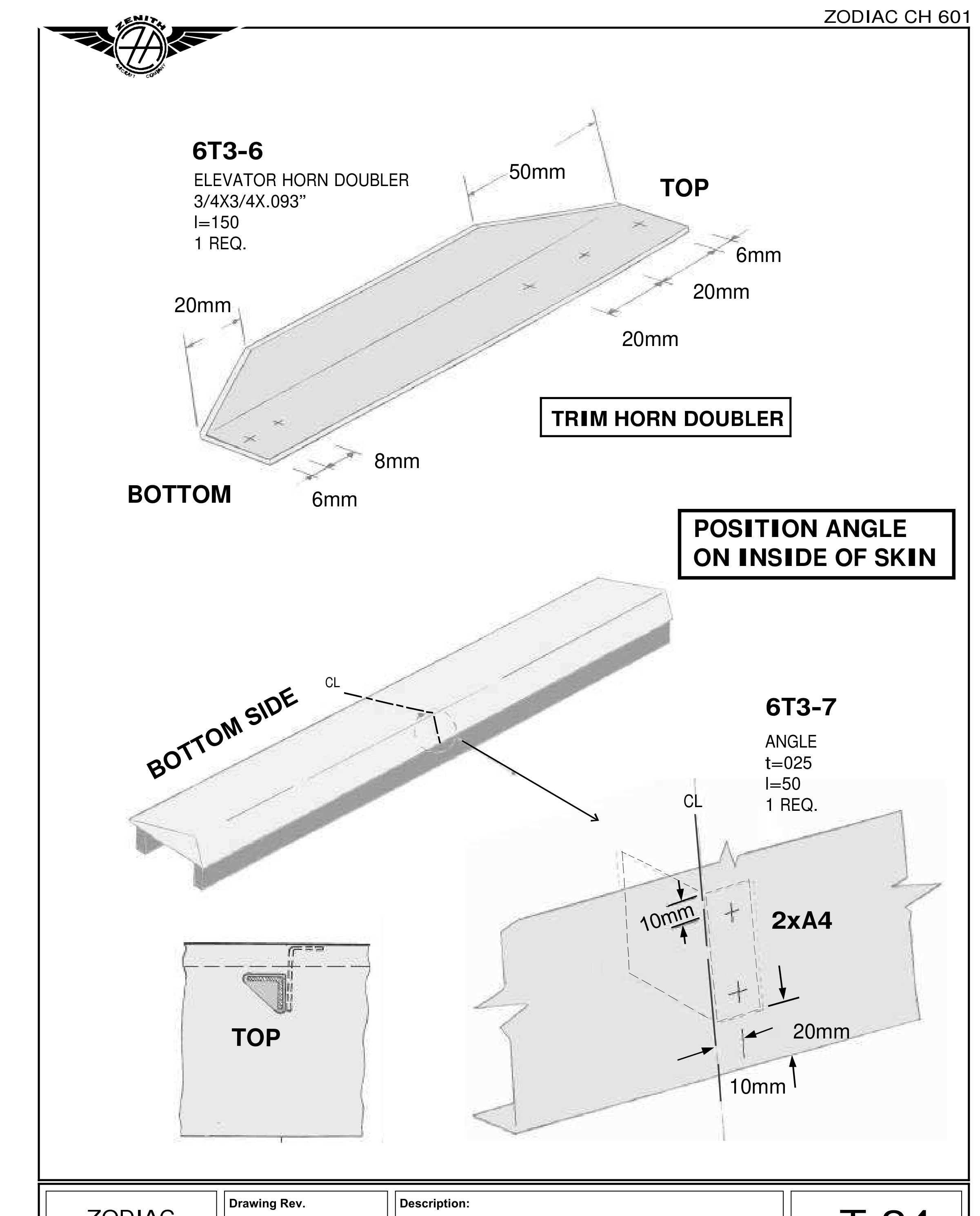
T-24: сужение усилителя 6T3-6 и разметка внутреннего 6T3-7. Верхний и нижний концы имеют разные размеры; вид сохраняет ориентацию исходника.
Шаг 7. В старом тексте общая длина 6T3-6 — 150 мм. При ориентации по T-24 от правого конца отмечают 50 мм, от левого 20 мм, линейкой соединяют отметки с концами для сужения верхней и нижней полок. Пилят снаружи линии при закреплённой детали, затем последовательно доводят крупным, средним и мелким напильником; острые углы слегка скругляют. Источник предупреждает: при механизированной обработке чрезмерное усилие и нагрев могут изменить состояние сплава 6061-T6.
Поздняя сводка HD 09/2003 меняет 6T3-6 REV 1 с длины 150 на 160 мм и удаляет прежние размерные указания положения 55 и 22. Поэтому длина 150 мм здесь является записью старого руководства, не универсальной заготовкой для любой редакции HD.
Шаг 8. Уголок 6T3-7 ставят внутри обшивки справа от оси самолёта на передней стороне. По тексту два крепления проходят через переднюю полку и два — в усилитель. Для разметки уголок сначала прикладывают снаружи, центрируют по высоте, угольником проверяют выход боковой полки на ось самолёта и обводят полку шириной 20 мм.
На обшивке и уголке отмечают середины полок, крайние отверстия в 10 мм от торцов. В обшивке сверлят два №40, в передней полке уголка — пока нижнее. Уголок ставят внутрь на нижнем Cleco, изнутри выставляют угольником по нижней стороне обшивки и удерживают сверху струбциной 2 дюйма. Перед сверлением верхнего отверстия должна быть видна осевая линия полки.
T-24 подписывает усилитель 3/4 × 3/4 × .093 дюйма, длину 150; уголок .025, длину 50, на чертеже его два крепления показаны как A4. Вырезы и концы имеют дополнительные размеры 6 и 8 мм у своих линий. Сводка 08/2004 перерисовывает скрытые линии 6T3-7 — старая схема не объявляется поздней.
Сверить с исходным текстом
ZENITH AIRCRAFT COMPANY
Print Date: 10/24/01
ZODIAC CH 601
ELEVATOR HORN DOUBLER & ANGLE
T-23
Taper the top and bottom flange of the Elevator Horn Doubler.
Cleco the Angle inside the Skin, the Double will rivet to the side of the Angle. Establish the
position of the Angle to hold the Doubler in a vertical position through the top and bottom cutout
openings in the Skin.
7. The overall length of the Elevator Horn Doubler 6T3-6 is 150mm. With the Doubler
positioned as shown on page T-24 mark off 50mm from the right end and 20mm from the
left end of the of the Doubler. Hold a ruler flat on the Doubler flange to draw a connecting
line from the mark to the end of the Doubler.
SAW: Clamp the Doubler over the edge of the workbench or in a vise to saw on the outside
of the line. File to remove the saw marks while the Doubler is still firmly clamped in place.
At first use a coarse file to help remove material faster, then use a medium cut file and then
transition to a fine double cut file to end up with a smooth finish. Remember to gently round
off the sharp corners on both flanges.
COMMENT: When power tools are used, keep the cutting surfaces sharp to avoid excessive
feed forces or pressure which has a tendency to significantly raise the temperature and alter
the tempered nature of the 6061-T6 alloy.
8. Position the Angle 6T3-7 on the right side of the aircraft center line on the front side of the
Elevator Skin. The Angle fits inside the Skin with 2 rivets in the front flange and 2 rivets in
the Doubler.
PILOT HOLES: Hold the Angle on the outside of the Skin on the right side the aircraft
centerline, centered up and down on front of the Elevator skin (to help intersect the
projection of the side flange with the aircraft center line hold a square along the side flange
of the Angle). Trace around the 20mm wide flange to mark the position of the Angle on the
Skin. Remove the Angle and make the rivet line in the middle of the flange on both the Skin
and the Angle. Locate the end holes 10mm in from the ends of the flange on the Skin and on
the Angle. Pre-drill the two holes in the Skin with a #40 drill bit. Also drill the bottom hole
in the front flange of the Angle.
FIRST HOLE: Position the Angle inside the Skin with a Cleco through the bottom hole.
ALIGNMENT: Hold a square inside the Elevator Skin referenced on the bottom side, rotate
the angle until square and secure with a 2” clamp from the top. Before drilling check that the
flange center line is visible through the pre-drilled pilot hole.
Страница 12 исходного PDF
Верхний и нижний кабанчики
Верхний и нижний кабанчики · исходный лист 13 · Открыть крупно
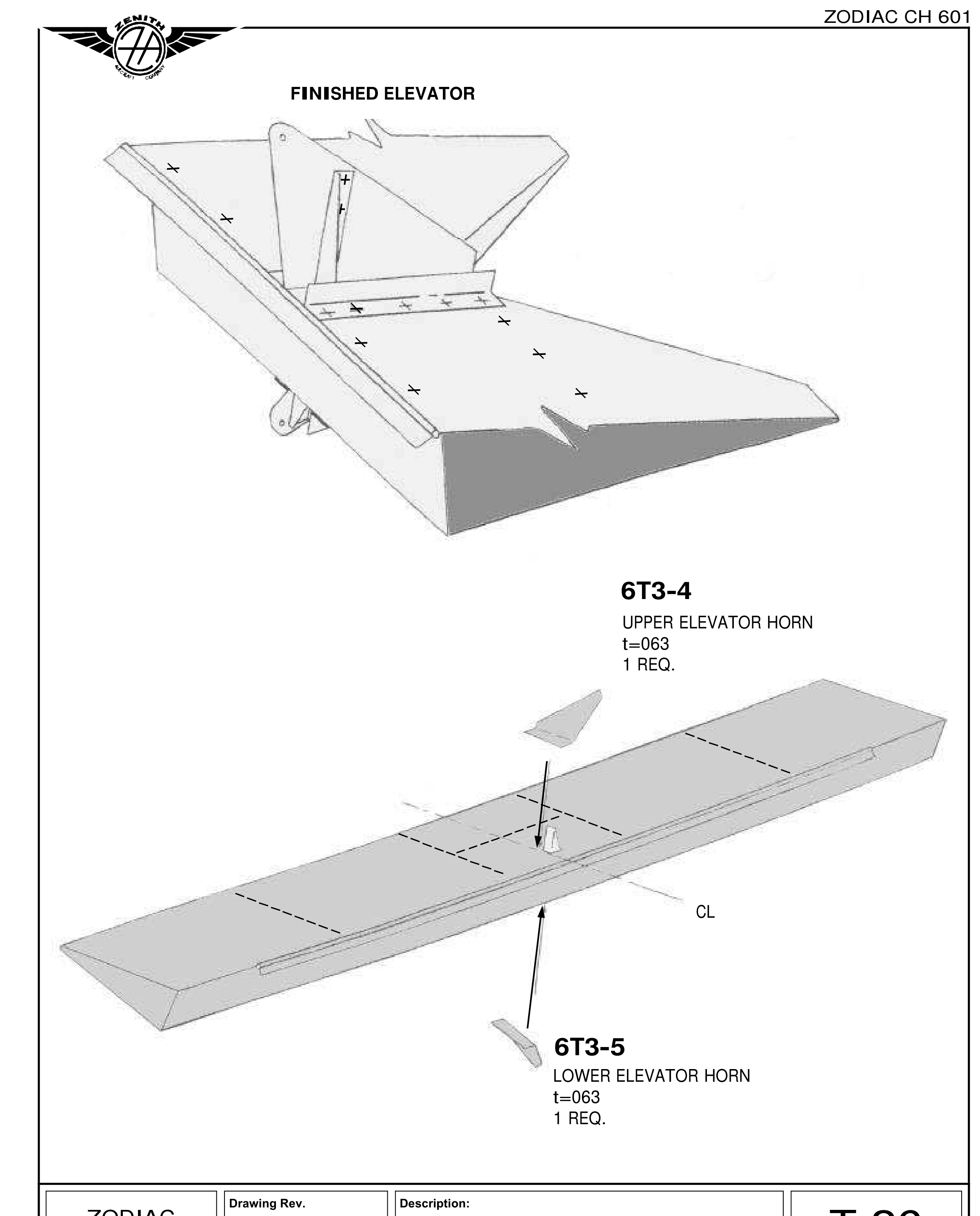
T-26: расположение верхнего 6T3-4 и нижнего 6T3-5 относительно обшивки и оси самолёта.
Верхний и нижний кабанчики · исходный лист 15 · Открыть крупно
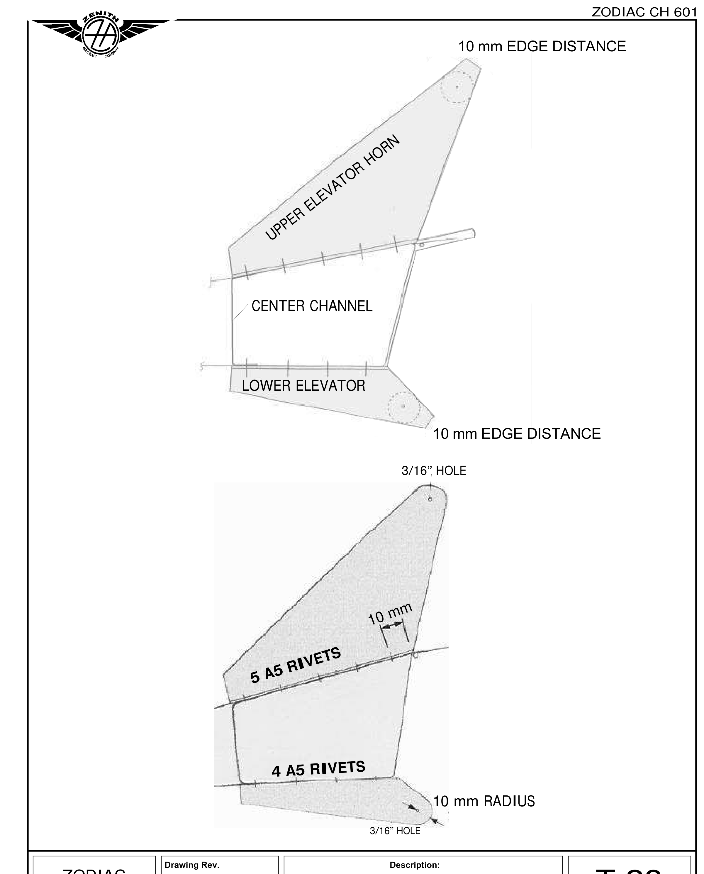
T-28: отдельные верхний и нижний кабанчики, отверстия 3/16 дюйма, расстояния до края и разные группы A5. Поздняя геометрия нижнего кабанчика уточнена отдельно в тексте.
В этой редакции центры отверстий 3/16 дюйма под тросы на обоих кабанчиках лежат на радиусе 100 мм относительно штыря петли. Верхний центр — на продолжении переднего наклона обшивки; нижний — на 10 мм впереди оси штыря. Условная ось штыря здесь совмещена с передней стороной обшивки.
Шаг 9. Усилитель вставляют через обшивку и временно прижимают верхний 6T3-4 и нижний 6T3-5. Штырь петли можно вынуть для точной привязки радиуса. Верхнее отверстие находят линейкой по передней стороне обшивки, отмеряя 100 мм от оси петли. Кабанчик сдвигают до расстояния не менее 10 мм от центра отверстия до передней, верхней и задней кромок. Для нижнего на линейке размечают смещение 10 мм и сохраняют не менее 10 мм до передней, нижней и задней кромок.
Задние концы кабанчиков должны быть заподлицо с торцом 6T3-2, перед верхнего — с передней кромкой обшивки; при необходимости его подрезают. Центры кернят, сверлят пилотные и затем 3/16 дюйма.
Шаг 10. Кабанчики соединяют Cleco с передней полкой обшивки и одним задним креплением к 6T3-2. Угольником по оси проверяют положение, радиус 100 мм и продольную ориентацию. В верхнем сверлят пять равномерно расположенных отверстий №20, в нижнем четыре.
На T-26 оба кабанчика подписаны толщиной .063 дюйма; T-28 показывает 5 A5 и 4 A5, радиус 10 мм и расстояние до края 10 мм. Поздняя сводка 09/2003 меняет у 6T3-5 REV 1 положения 95→92 и 22→24 мм, заднюю кромку 28→31 мм. Эти поправки требуют соответствующего чертежа и не превращаются в перенос всех размеров из T-25 в позднюю деталь.
Сверить с исходным текстом
ZENITH AIRCRAFT COMPANY
Print Date: 10/24/01
ZODIAC CH 601
UPPER & LOWER ELEVATOR HORNS T-25
The center of the 3/16” hole for the cable attachment in both the Upper and the Lower Elevator
Horn are on a 100mm radius centered on the Piano Hinge pin (the 100mm measurements sets the
up and down position of the hole). For the Upper Horn the center of the hole is on the extension
of the front angle of the Elevator Skin: locate the position of the hole simply by holding a
straight edge along the front of the Skin and measuring up 100mm from the center of the piano
hinge along the edge of the straight edge. The center of the bottom hole is 10mm forward of the
center of the piano hinge pin (the center of the piano hinge pin is taken to be inline with the front
of the Elevator Skin.
9. Position the Doubler through the Skin to temporarily clamp the Upper Elevator Horn 6T3-4
and Lower Elevator Horn 6T3-5 to the Doubler.
Center of the Piano Hinge pin: Pull out the pin from the Piano hinge to better locate the
center of the 100mm radius.
3/16” hole in the Upper Elevator Horn: Hold a straight edge along the front of the Skin to
overlap on top of the Upper Elevator Horn. Reference the ruler on the center of the Piano
Hinge and measure up 100mm along the front edge of the straight edge. Keep adjusting the
fore and aft position of the Upper Elevator Horn until there is at least a 10mm edge distance
from the center of the upper 3/16” cable attachment to the front, top and aft edge of the Horn.
3/16” hole in the Lower Elevator Horn: On the straight edge, draw a 10mm offset line from
the side in contact with the front of the Skin. Once again, allow the straight edge to overlap
the Horn, keep adjusting the fore and aft position of the Lower Elevator Horn until there is at
least 10mm edge distance from the center of the 3/16” hole to the front, bottom, and rear edge
of the Horn.
CHECK: The aft end of the Upper and Lower Horns are flush with the end of the Channel
6T3-2. The front end of the Upper Horn is flush with the front edge of the Skin – trim the
front edge if necessary.
DRILL: For better accuracy center punch the center of the 3/16” hole, drill first with a pilot
size hole, then open up with a 3/16” diameter drill bit.
10. Cleco the Upper and Lower Elevator Horn to the Elevator flange (Skin) and to the Channel
6T3-2 with one rivet at the rear.
POSITION: Hold the corner of a carpenter square on the aircraft center line, slide the Horn
until it touches the side of the square. Check the 100mm radius from the center of the piano
hinge and the fore and aft alignment.
DRILL/CLECO: Drill 5 #20 holes evenly spaced in the top Horn and 4 #20 holes (evenly
spaced) in the bottom Horn.
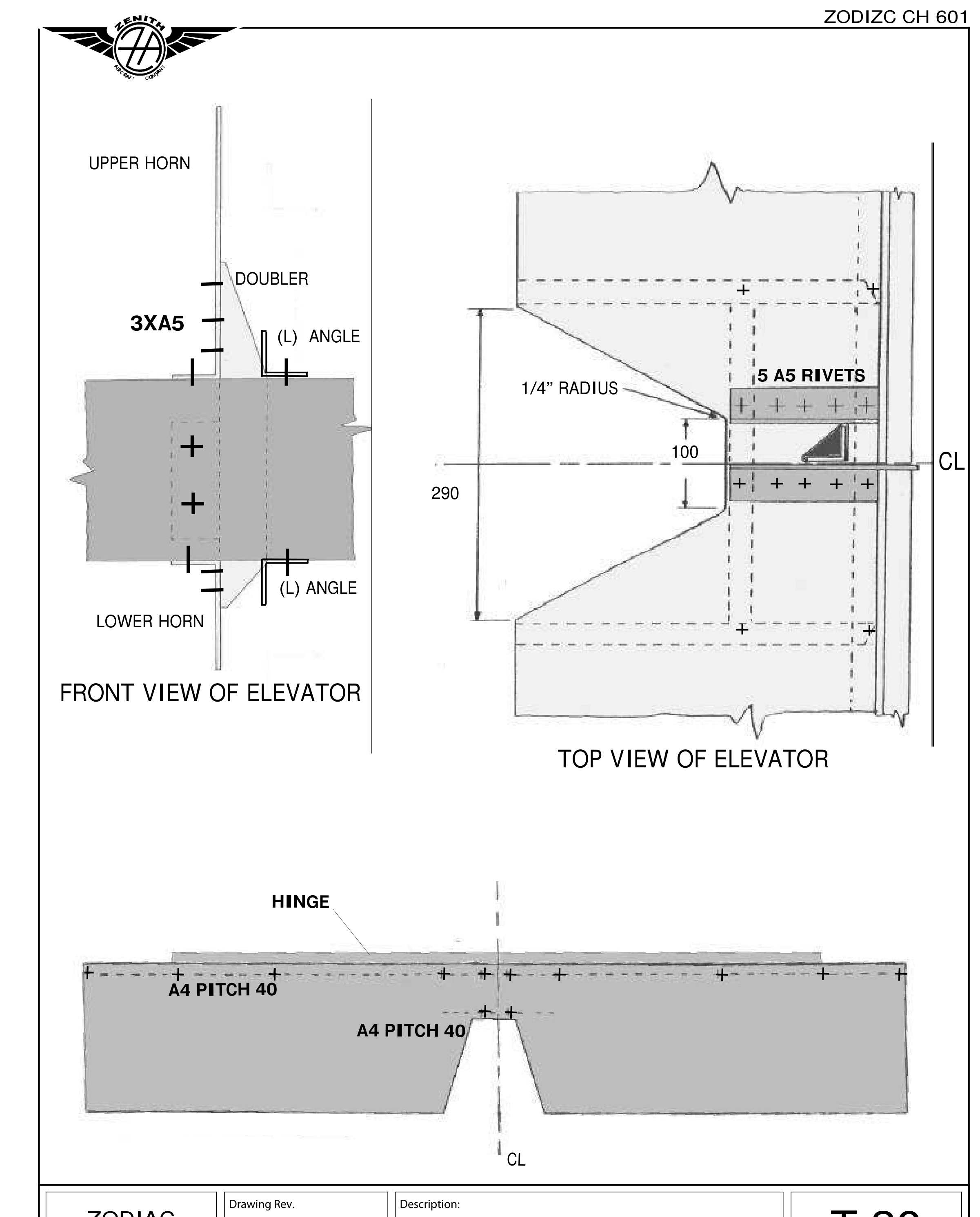
T-30: передний вид усилителя с верхним и нижним L-профилями и вид сверху на вырез под руль направления. Слева подписана отдельная группа 3 × A5 у усилителя, справа — 5 A5; они принадлежат своим соединениям.
Вводная строка T-27 задаёт верх усилителя на 55 мм выше обшивки и низ примерно на 25 мм ниже. Как отмечено ранее, поздняя сводка удаляет старые размерные привязки; их не применяют к REV 1 автоматически.
Шаг 11. Размечают три заклёпки в верхней части усилителя к боку верхнего кабанчика и две в нижней к боку нижнего. Детали прижимают, выравнивают отступы первого отверстия от обшивки сверху и снизу; сверлят №20 и ставят Cleco. Текст ссылается на 6T3-6.
Шаг 12. Верхний кабанчик и усилитель временно снимают, приоткрывают верх обшивки. Усилитель возвращают на Cleco к нижнему кабанчику и прижимают к 6T3-7. Соединение с уголком — два отверстия №20.
Шаг 13. Верхний кабанчик и усилитель ставят снова. Сверху и снизу размещают по L-профилю от переда обшивки до заднего края 6T3-2, полкой к усилителю, с наружной от него стороны. Сверлят четыре №20 и ставят Cleco.
Шаг 14. Заканчивают ряд через 6T3-2 и обшивку: шаг 40 мм, сверло №30. На T-30 видно отдельное крепление L-профилей и обшивки A4 с шагом 40, а кабанчики имеют свои A5; эти группы не взаимозаменяются.
Сверить с исходным текстом
ZENITH AIRCRAFT COMPANY
Print Date: 10/24/01
ZODIAC CH 601
L Angles
T-27
Cleco the Elevator Horn Doubler to the side of the Angle 6T3-7: set the top 55mm above the
Skin and check that the bottom extends approximately 25mm below the Skin.
Cleco a length of L Angle from the front flange of the Elevator Skin to the Channel 6T3-2 on the
top and bottom side of the Elevator. The L Angles are positioned on the outboard side of the
Doubler. (see page T-30)
11. Layout the 3 rivets in the upper portion of the Doubler (to rivet into the side of the Upper
Horn) and the 2 rivets in the lower portion of the Doubler (to rivet into the side of the Lower
Horn) as shown on drawing 6T3-6
POSITION: Clamp the Doubler to the Horn. Check and adjust the position of the Doubler
for equal distance between the Skin on the top and bottom side with the first hole in the
Doubler.
DRILL/CLECO: Drill with a #20 and Cleco the Doubler to the side of the Horns.
12. Cleco the Elevator Horn Doubler to the side of the Angle 6T3-7
POSITION: Remove the Doubler and Upper Horn to open the top side of the Elevator Skin.
Holding the Skin open, Cleco the Doubler to the Bottom Horn. Clamp the Doubler to the
Angle 6T3-7 (the Angle can also be installed at this stage).
DRILL/CLECO: 2 #20 holes.
13. Reinstall the Upper Horn and Doubler. Position a length of L Angle with the flange up
against the Doubler to span from the front of the skin to the aft edge of the Channel 6T3-2.
POSITION: One L Angle on the top side and one on the bottom side.
DRILL/CLECO: 4 #20 holes.
14. Finish drilling the rivet line through the Channel 6T3-2 and the Elevator Skin with Pitch 40
and using #30 drill.
Страница 16 исходного PDF
Вырез под руль направления и завершение сборки
Вырез под руль направления и завершение сборки · исходный лист 17 · Открыть крупно
T-30: симметричная относительно оси выемка под руль направления общей шириной 290/100 мм. Это другой вырез, чем смещённые влево прорези под усилитель кабанчиков.
Шаг 15. Пока руль высоты собран на Cleco, от оси размечают вырез под руль направления: полная ширина у задней кромки 290 мм, у центрального профиля 100 мм. Центры угловых разгрузочных отверстий 1/4 дюйма ставят так, чтобы края касались линий выреза. Сначала делают черновой рез, затем по линии и доводят напильником, включая заусенцы и узкие остатки после ножниц.
Разночтение единиц на T-30: подпись у угла говорит «1/4 inch radius», тогда как текст T-29 задаёт разгрузочное отверстие 1/4 дюйма. Радиус и диаметр — разные величины; их не объявляют одинаковым размером и проверяют по применимому листу.
Шаг 16. Сборку разбирают, снимают заусенцы со всех отверстий, при выбранной технологии наносят защиту от коррозии, затем собирают на Cleco и заклёпывают. Геометрию и крепёж разных редакций перед окончательной клёпкой не смешивают.
Сверить с исходным текстом
ZENITH AIRCRAFT COMPANY
Print Date: 10/24/01
ZODIAC CH 601
RUDDER CUTOUT
T-29
Make the cutout while the Elevator assembly is Clecoed together.
15. Mark the cutout from the aircraft center line.
LAYOUT: 290mm is the overall width of the cutout at the trailing edge.
100mm is the overall width at the Channel
CORNER RELIEF HOLES: Find the center of the ¼” corner relief holes to position
the edge of the hole tangent with the cutout lines.
SNIP: First do a rough cut then a final cut on the line.
FILE: File the rough edges including any slivers left behind from the snips.
16. Disassemble the Elevator assembly to deburr the holes and to apply the corrosion protection
if desired. Reassemble with Clecos and rivet.
10/24/01: ZAC Engineering/601 manual/ELEVATOR.doc