
Стабилизатор: лонжероны, нервюры и обшивка

Редакция и применимость

Перевод 30 операций stabilizer.pdf, печать 24.10.2001. Обзорные листы руководства имеют собственные даты 1996–2000 годов. Для CH 601 HD сверяются HD-усилители и сводки изменений 09/2003 и 08/2004. Старый текст и поздние изменения показаны раздельно: они не образуют автоматически полный актуальный комплект. Названия и количество деталей, указанные в ведомости и на схемах по-разному, отмечены ниже.

Руководство обозначено как DRAFT: оно поясняет сборку, но не заменяет применимые чертежи и не является шаблоном изготовления. Файлы найдены в исторической коллекции HDS, но эти конкретные руководства относятся к семейству CH601; материал HD сверяется отдельно, без переноса HDS-крыла или UL-толщин.

Страница 4 исходного PDF

Задний лонжерон и его усилители
Задний лонжерон и его усилители · исходный лист 5
Задний лонжерон и его усилители · исходный лист 5 · Открыть крупно

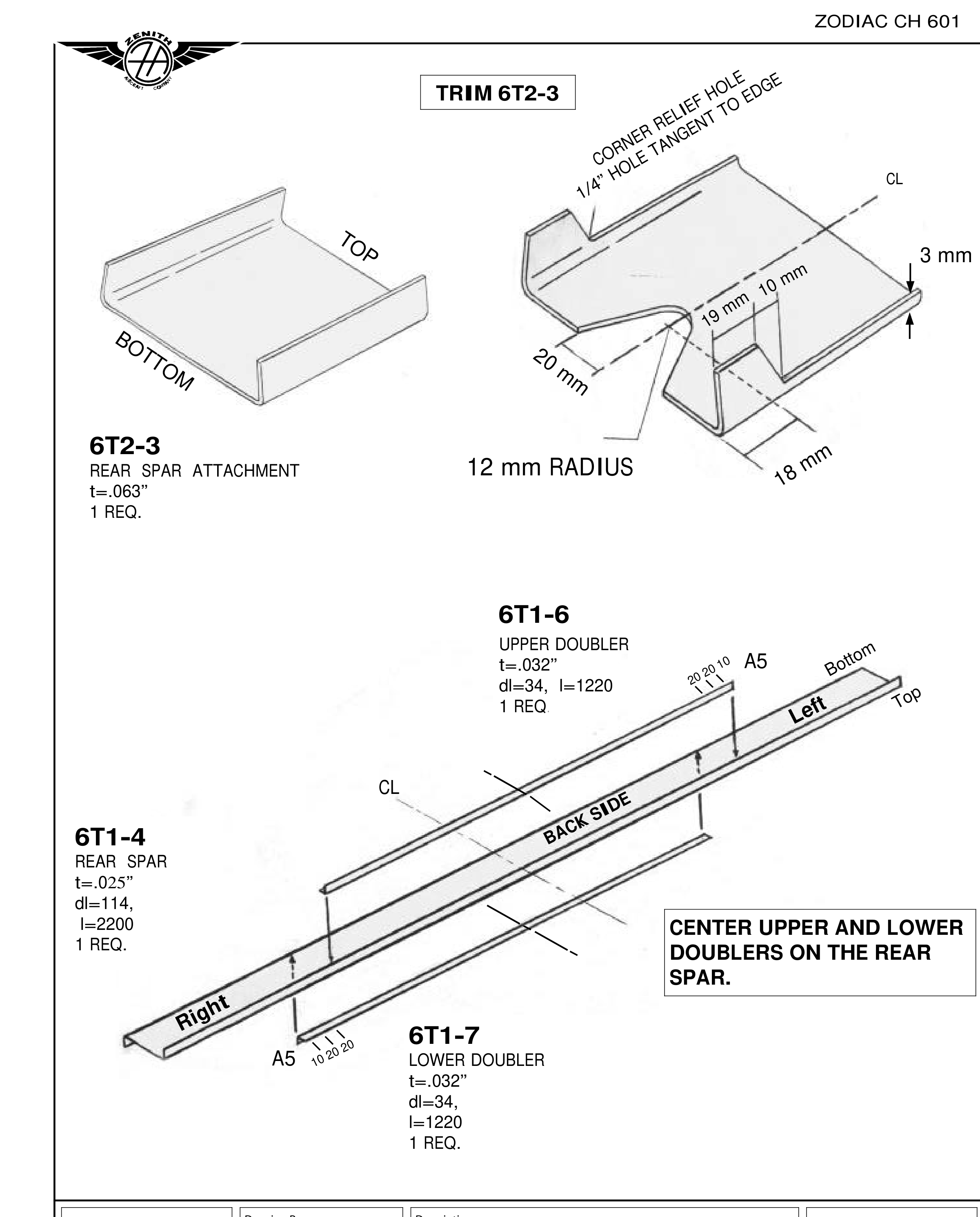
T-36: подрезка 6T2-3, верх/низ Z-лонжерона и центрирование усилителей. На рисунке дополнительно подписаны 18 и 20 мм у своих выносных линий; их не заменяют значением 29 мм из другой базы текста.

Задний узел крепления ставится с тыльной стороны лонжерона. Боковые полки в зоне перекрытия подрезают с 22 до 3 мм для прохода передней нижней части руля высоты при отклонении вниз. Вводная строка говорит о вырезе в 20 мм от оси под нижний трос при отклонении вверх; она относится к своей базе, а не заменяет остальные размеры рисунка.

Шаг 1. На 6T2-3 размечают линию 3 мм над стенкой, нижний угол в 29 мм от низа и верхнюю точку 19 мм, соединяют наклонной линией. Разгрузочные отверстия 1/4 дюйма касаются сторон выреза; их центры выше линии 3 мм, примерно в 32 мм от низа. Сначала сверлят отверстия, затем пилят полки. Деталь защищают от губок тисков, у отверстия уменьшают усилие пилы, чтобы не надрезать противоположную сторону. Доводят напильником. В центральном проёме радиус 12 мм можно обработать полукруглым напильником вместо сверления отверстия 22 мм.

Шаг 2. У заднего лонжерона 6T1-4 отмечают верх и перед: верхняя полка закрыта на 5° и направлена назад, нижняя открыта на 5° относительно 90° и направлена вперёд. Ось самолёта размечают в 1100 мм от концов перпендикулярно нижней полке.

Шаг 3. Верхний усилитель 6T1-6 ставят под верхней полкой. На полке, перекрывающей стенку, отмечают ряд; боковую полку сверлят позже через обшивку. Ось усилителя — в 610 мм от концов. Крайние отверстия — в 10 мм от концов, два следующих через 20 мм. Оси совмещают и сверлят по три отверстия на каждом конце через стенку, ставят Cleco.

Шаг 4. Нижний усилитель 6T1-7 выставляют по нижней полке так же: ряд, ось, крайнее отверстие 10 мм и следующие через 20 мм; после центрирования и зажима сверлят по три отверстия на концах.

Разночтение толщин: ведомость T-34 задаёт 6T2-3 толщиной .040 дюйма, а T-36 — .063; усилители 6T1-6/6T1-7 в ведомости HD имеют .040, на T-36 — .032. Это разные записи источника, не разрешение выбирать произвольную толщину. На T-36 задний лонжерон .025, развёртка dl=114 и длина 2200; усилители длиной 1220. Сводка 09/2003 меняет dl 114→112 и отдельные HD-длины 1220→1219; в 08/2004 для 6T1-4 REV 1 полка меняется 18→19 мм, dl 112→114. Размеры разных редакций не суммируют.

Сверить с исходным текстом
ZENITH AIRCRAFT COMPANY Print Date: 10/24/01 ZODIAC CH 601 REAR SPAR DOUBLERS T-35 The Rear Spar Attachment fits on the back side of the Rear Spar in order to bolt the Stabilizer to the fuselage. Before installing, the side flanges are cut down from 22mm to 3mm on the overlapping portion with the Rear Spar – this is to make clearance for the front bottom of the elevator during down deflection. The 20mm cutout from the centerline in the bottom of the Rear Spar Attachment is to make room for the bottom elevator cable during up deflection. The Upper and Lower Doubler are Clecoed to the Rear Spar before positioning the Center Ribs. Later, when the Center Ribs are positioned they will overlap on top of the Doubler with a rivet through the middle of the overlap of the Rib flange with the Doubler. 1. LAYOUT the cutout on the Rear Spar Attachment 6T2-3: mark a 3mm offset line above the web (the web is the flat area between the flanges). From the bottom, mark the corner at 29mm and the top at 19mm, connect the slop line (bottom left on drawing 6T2 shows the side flange cutout reference from the top edge) CORNER RELIEF HOLE: The edges of the corner relief holes are tangent to the sides of the cutout. Carefully center-punch the center of each ¼” hole above the 3mm line (approximately 32mm from the bottom). Drill the holes before cutting the side flange. SAW: With the part clamped in a vise (protect the part from the sharp edges of the steel vise jaws) use a hacksaw to carefully cut above the line. Be prepared to back off the pressure on the saw when it cuts through the relief hole or it will cut and mark into the opposite side! File to the line to remove the saw marks for a smooth finish. For the middle opening, the 12mm radius can be contoured with a large half round file instead of drilling a large 22mm hole. 2. Identify and label the top and front side of the Rear Spar 6T1-4: the top flange is 5 degrees closed and points toward the rear. The bottom flange of the “Z” shaped spar points to the front and is 5 degrees open (larger than 90degrees). Mark the aircraft center at 1100mm from the ends perpendicular to the bottom flange. 3. With the Rear Spar 6T1-4 on the workbench position the Upper Doubler 6T1-6 underneath the top flange. LAYOUT: Mark the rivet line on the Upper Doubler on the flange that overlaps on top of the spar web. The side flange is drilled later from the top through the skin. Also mark the aircraft center line at 610mm from the ends. The end holes are at 10mm from the ends of the Doubler with the next two 20mm spacing. CLAMP: To center the Doubler on the Spar, super-impose the centerline of the Doubler with the aircraft centerline of the Rear Spar. DRILL & CLECO: Drill & Cleco the three holes at each ends of the Doublers into the Rear Spar web. 4. Cleco the Lower Doubler 6T1-7 to the bottom flange of the Rear Spar 6T1-4 CLAMP: Mark the rivet line, locate the aircraft center line, layout the end holes at 10mm from the ends and the next two holes as 20mm spacing. Center the Doubler on the Rear Spar clamp before drilling the three holes at each ends into the Rear Spar Web.

Страница 6 исходного PDF

Заднее крепление и шаблон станций нервюр
Заднее крепление и шаблон станций нервюр · исходный лист 7
Заднее крепление и шаблон станций нервюр · исходный лист 7 · Открыть крупно

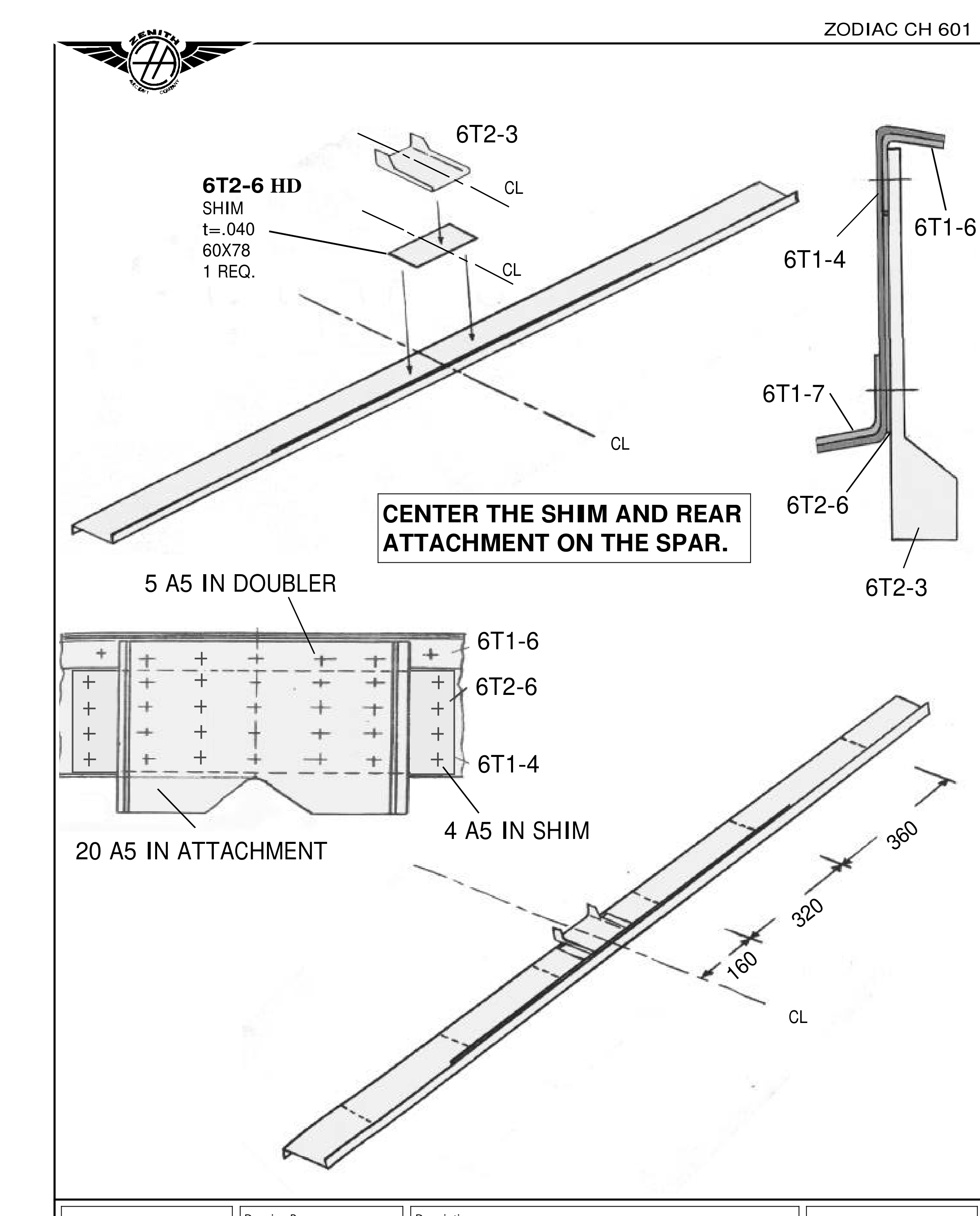
T-38: центрирование прокладки и заднего крепления, станции 160/320/360 и раскладка разных групп A5. Шаблон — инструмент переноса станций, не профиль детали.

Шаг 5. Узел 6T2-3 прижимают поверх верхнего усилителя 6T1-6, между ним и стенкой лонжерона вводят прокладку 6T2-6 толщиной .040 дюйма. Верх узла доходит до касательной гиба усилителя; боковины перпендикулярны низу лонжерона, детали центрированы. В тексте указаны 25 A5, пять рядов по пять: верхний и нижний через усилители, три промежуточных через прокладку. По обе стороны дополнительно указано по четыре A5 вертикальным рядом через прокладку и стенку. Сверлят №20 и ставят Cleco.

Шаг 6. Для симметричных станций делают шаблон из полосы длиной 4 фута, шириной около 30 мм, либо мерной рейки. От одного явно отмеченного нулевого конца задают станции 160, 320 и 360 мм. Ноль совмещают с осью самолёта. Тот же шаблон используется для переднего лонжерона 6T1-3 и обшивки 6T2-4.

Шаг 7. Шаблоном отмечают станции на верхнем и нижнем усилителях справа и слева. Между станциями и между задним креплением и первой станцией 160 делят расстояния под шаг 40 мм. Усилитель плотно прижимают к полке и сверлят №20. Отверстия на самих станциях пока не сверлят: их выполняют позже по середине перекрытия полки нервюры с усилителем.

На T-38 прокладка 6T2-6 HD подписана .040, 60 × 78 мм. Подписи «20 A5 in attachment» и «5 A5 in doubler» разделяют соединения на виде; они не являются основанием ещё раз добавить 25 к 20 и 5. Сводка 05/2003 отдельно меняет вырез и радиус переднего края 6T2-3: старый рисунок здесь оставлен с его датой.

Сверить с исходным текстом
ZENITH AIRCRAFT COMPANY Print Date: 10/24/01 ZODIAC CH 601 REAR SPAR ATTACHMENT T-37 A Shim of the same thickness as the Upper Doubler fits underneath the Rear Spar Attachment. Finish drilling the Doublers to the Rear Spar by dividing the distance between the Center Ribs stations for a pitch of 40mm. The holes at the Rib stations are drilled later on the middle of the overlap of the Rib flange with the top and bottom Doublers. 5. CLAMP the Rear Spar Attachment 6T2-3 to overlap on top of the Upper Doubler 6T1-6. Slide the .040 Shim 6T2-6 in-between the Spar web and the Attachment. CHECK: a) The top of the Rear Spar Attachment stops at the bend tangent line of the Upper Doubler. b) The sides are at 90degrees to the bottom of the Rear Spar. c) The parts are centered on the aircraft center line (equal distance from the left or right ends of the Spar). LAYOUT: a) Total of 25 A5 rivets into the Attachment (five rows of 5A5): the top and bottom rows are through the Doublers with 3 rows into the Shim. b) 4 A5 rivet in one vertical column of rivets into the Shim and Spar on both sides of Rear Spar Attachment. DRILL & CLECO: With #20 6. RIB POSITION TEMPLATE: The left and right sides of the Stabilizer are symmetrical, also the rivet pitch is the same in both the Top and Bottom Doublers. On a 4ft sheet metal strip (approximately 30mm wide) or on a yard stick, layout the following rib stations at: 160, 320 and 360mm . Clearly label the zero reference end from which the rib stations are set — the template is used by lining up the zero reference with the aircraft center line. This template will also be used to layout the rib stations on the Front Spar 6T1-3 and on the Stabilizer Skin 6T2-4 7. LAYOUT: Use the RIB POSITION TEMPLATE with the zero reference on the aircraft centerline to mark the ribs station lines on both Doublers (top and bottom right and left sides). It may be easier to remove the Rear Spar Attachment to lay the zero end of the template on the Rear Spar center line. RIVET PITCH: Divide the distance between the rivet station for a pitch of 40mm. (using a 40mm pitch template). Also divide the distance between the Rear Spar Attachment and the first Rib at station 160 for a pitch of 40mm. DRILL & CLECO: #20 drill bit. Before drilling, clamp or firmly pinch the Doubler against the Rear Spar flange. Wait to drill the holes at the Rib stations, they are drilled later when the Ribs are positioned to center the hole on the middle of the Rib flange with the overlap of the Doublers.

Страница 8 исходного PDF

Передний лонжерон и узлы крепления
Передний лонжерон и узлы крепления · исходный лист 9
Передний лонжерон и узлы крепления · исходный лист 9 · Открыть крупно

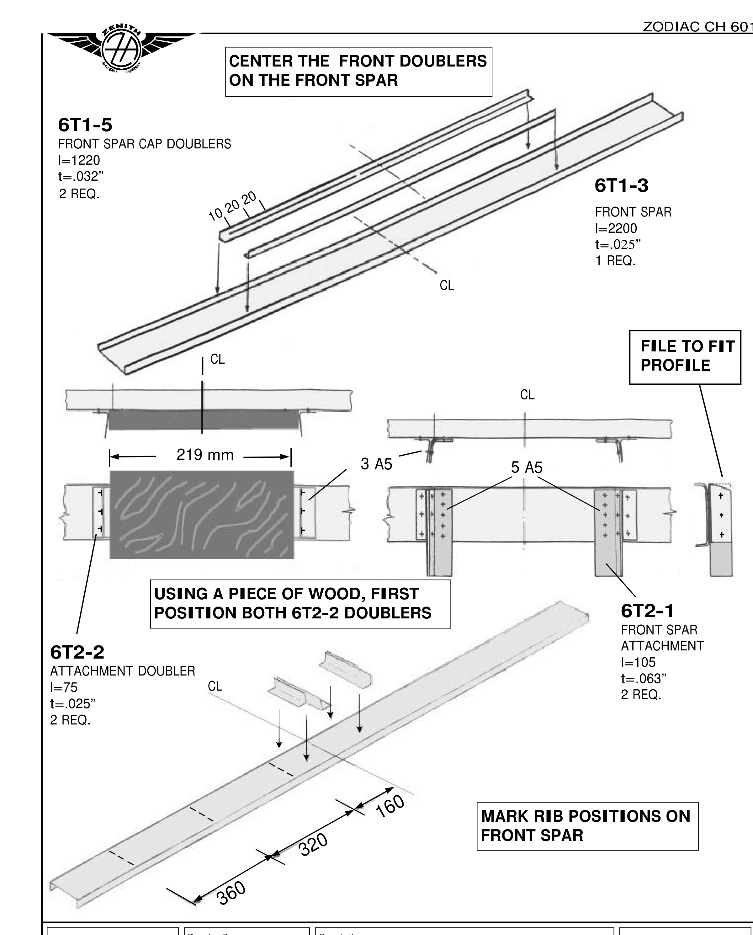
T-40: усилители 6T1-5, фанерный шаблон 219 мм, 6T2-1 и 6T2-2. Отдельно показано подтачивание под профиль и станции нервюр.

Шаг 8. Усилители поясов 6T1-5 ставят к внутренней стенке переднего лонжерона 6T1-3. Боковые полки сверлят позже через обшивку 6T2-4. Ряд размечают по середине полки; ось — в 610 мм от концов. Крайнее отверстие 10 мм, ещё два через 20 мм. Усилители прижимают, на каждом выполняют шесть крайних отверстий №20 и ставят Cleco.

Шаг 9. Вырезают фанерный шаблон шириной 219 мм с параллельными сторонами под 90° к верхней кромке. Текст задаёт осевую линию в 110 мм от края — это округление не равно точной половине 219; фактическое центрирование проверяют по применимому листу.

Шаг 10. Шаблон прижимают к передней стороне лонжерона с совпадением осей. Угольником проверяют его торцы под 90° к лонжерону.

Шаг 11. Накладки крепления 6T2-2 выставляют по бокам шаблона и соединяют Cleco через три отверстия №20. Верхнее и нижнее проходят также через усилители с обратной стороны.

Шаг 12. Шаблон снимают, крепления 6T2-1 прижимают к полкам 6T2-2. Крайние отверстия проходят в пересечениях осей с усилителями поясов; между ними добавляют три равномерно расположенных отверстия №20.

Шаг 13. Верх накладок подгоняют напильником против контакта с обшивкой 6T2-4, клином снимая спереди примерно 3 мм. Во вводной строке переднее крепление названо уголком шириной 22 мм.

На T-40 6T1-5 имеет .032 дюйма и длину 1220, но ведомость HD даёт .040; передний лонжерон .025 и 2200; 6T2-1 — .063 и длина 105; 6T2-2 — .025 и длина 75. В 08/2004 у 6T1-3 REV 1 полка 18→19 мм и dl 120→122. Эти редакционные размеры не переносят в старый лист без проверки.

Сверить с исходным текстом
ZENITH AIRCRAFT COMPANY Print Date: 10/24/01 ZODIAC CH 601 FRONT SPAR DOUBLERS & ATTACHMENTS T-39 The Front Spar Cap Doublers are Clecoed against the inside web of the Front Spar Note: Unlike the Rear Spar, the top and bottom flanges of the Front Spar are bent at the same angle. The Front Spar Attachment is a 22mm wide angle reinforced by two Attachment Doublers. A plywood template the width of the fuselage (219mm) is used to correctly space the two Front Spar Attachment. 8. LAYOUT: The Front Spar Cap Doublers 6T1-5 are Clecoed inside the Front Spar 6T1-3 to the web, the side flanges are drilled later through the Stabilizer Skin 6T2-4. Mark the rivet line in the middle flange as well as the aircraft centerline at 610 from the ends. The end holes are at 10mm from the ends with the next two holes 20mm apart. CLAMP: Front Spar Cap Doublers to the side flange of the Front Spar. DRILL & CLECO: Drill & Cleco the six end holes with #20 in both Front Spar Cap Doublers. 9. Carefully cut a plywood template 219mm wide with parallel sides at 90 degrees to the top edge. LAYOUT: Draw the aircraft center line at 110mm down the middle of the plywood block.. 10. CLAMP the 219mm template on the front side of the Front Spar by superimposing center lines (the center line on the block over the aircraft center line on the Front Spar). CHECK: Use a square to check that the ends of the Block are at 90 degrees with the spar. 11. Drill and Cleco the Attachment Doublers 6T2-2 against the sides of the template with 3 #20. REMINDER: the top and Bottom holes are also through the Cap Doublers on the reverse side. 12. Remove the block and clamp the Spar Attachment 6T2-1 to the Doubler 6T2-2 flange. a) Position the top and bottom holes through on the intersection of center lines with Front Spar Cap Doublers. b) Add three #20 drilled holes evenly spaced between the two end holes. 13. FILE the top edge of the Doublers to avoid interference with the Stabilizer Skin 6T2-4 (wedge shaped taking off approximately 3mm at the front).

Страница 10 исходного PDF

Разметка лонжеронов и ориентация нервюр
Разметка лонжеронов и ориентация нервюр · исходный лист 11
Разметка лонжеронов и ориентация нервюр · исходный лист 11 · Открыть крупно

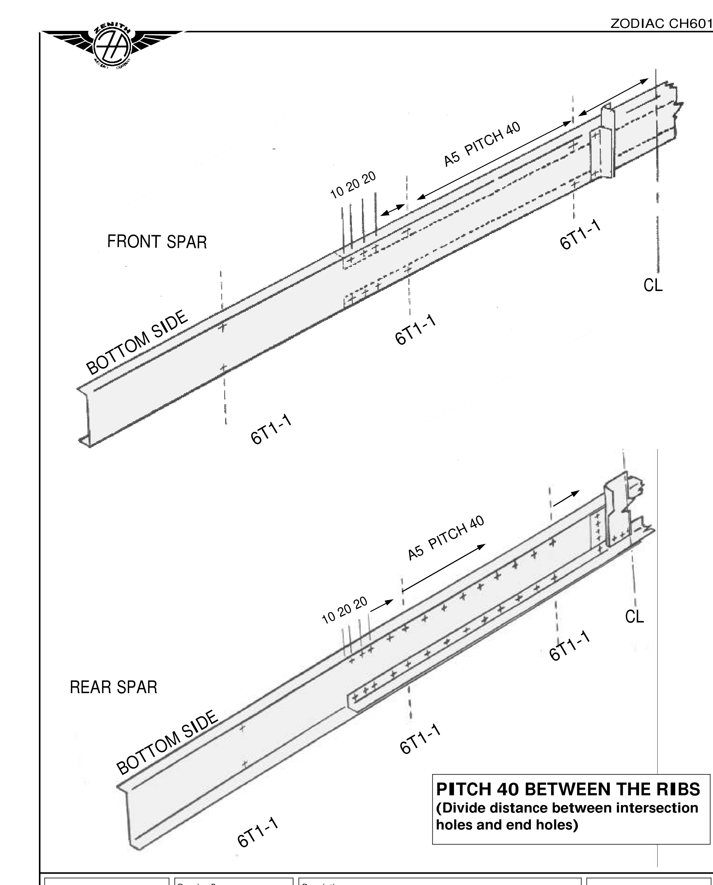
T-42: ряды A5 с шагом 40 мм между станциями и незаполненные места под полки нервюр. Номера 6T1-1 на старой схеме не подменяют перечень деталей конкретного комплекта.

Шаг 14. Шаблоном переносят станции на передний лонжерон и делят промежутки под шаг 40 мм. Усилители сверлят к стенке №20, оставляя отверстия станций для последующего сверления через нервюры. Линии станций продолжают в радиус гиба усилителя — они останутся видны за полкой при центрировании нервюры.

В этой редакции концевая нервюра 6T1-1 и промежуточные 6T1-2 симметричны относительно продольной оси. Передняя полка — под 90° к оси; передняя часть шире задней: передний лонжерон 6T1-3 имеет высоту стенки 84 мм, задний — 80 мм. Перед различают и по технологическому отверстию ближе к полке. При сравнении нервюр спинками друг к другу заднюю полку ставят в 18 мм от конца полной нервюры. Полки левых и правых нервюр направлены наружу.

Сверить с исходным текстом
ZENITH AIRCRAFT COMPANY Print Date: 10/24/01 ZODIAC CH 601 FRONT & REAR SPAR T-41 Finish drilling with #20 the Front Spar Cap Doubler to the Spar web by dividing the distance between the rib stations with pitch 40. 14. CLECO: Use the rib position template to layout the rib stations. Divide the distance in- between the rib stations using a 40mm pitch template. The holes at the Rib stations are drilled later through the rib flange. SUGGESTION: Extend the rib station line into the radius of the doublers. Later when the ribs are positioned, the line will be visible past the edge of the rib flange and is used to center the rib. NOTE on the STABILIZER RIBS: The End Rib 6T1-1 is symmetrical about the longitudinal axis, the Center Ribs 6T1-2 are also symmetrical about the longitudinal axis: the front flange is at 90 degrees to the longitudinal axis. The front of the Rib is wider than the rear of the Rib: the Front Spar 6T1-3 is 84mm wide and the Rear Spar is 80mm wide. The front of the Rib can be identified by the position of the tooling hole in the Rib web closest to the flange. A test is to hold the Center Ribs against the End Ribs back to back – hold the aft flange 18mm from the end of the full Rib as shown in the top left diagram on drawing 6T1 (the top flange of the Rear Zee is flush with the aft edge of the End Rib).Left and Right ribs are similar, the Ribs are positioned on the skeleton with the flanges facing outboard.

Страница 12 исходного PDF

Сборка каркаса стабилизатора
Сборка каркаса стабилизатора · исходный лист 13
Сборка каркаса стабилизатора · исходный лист 13 · Открыть крупно

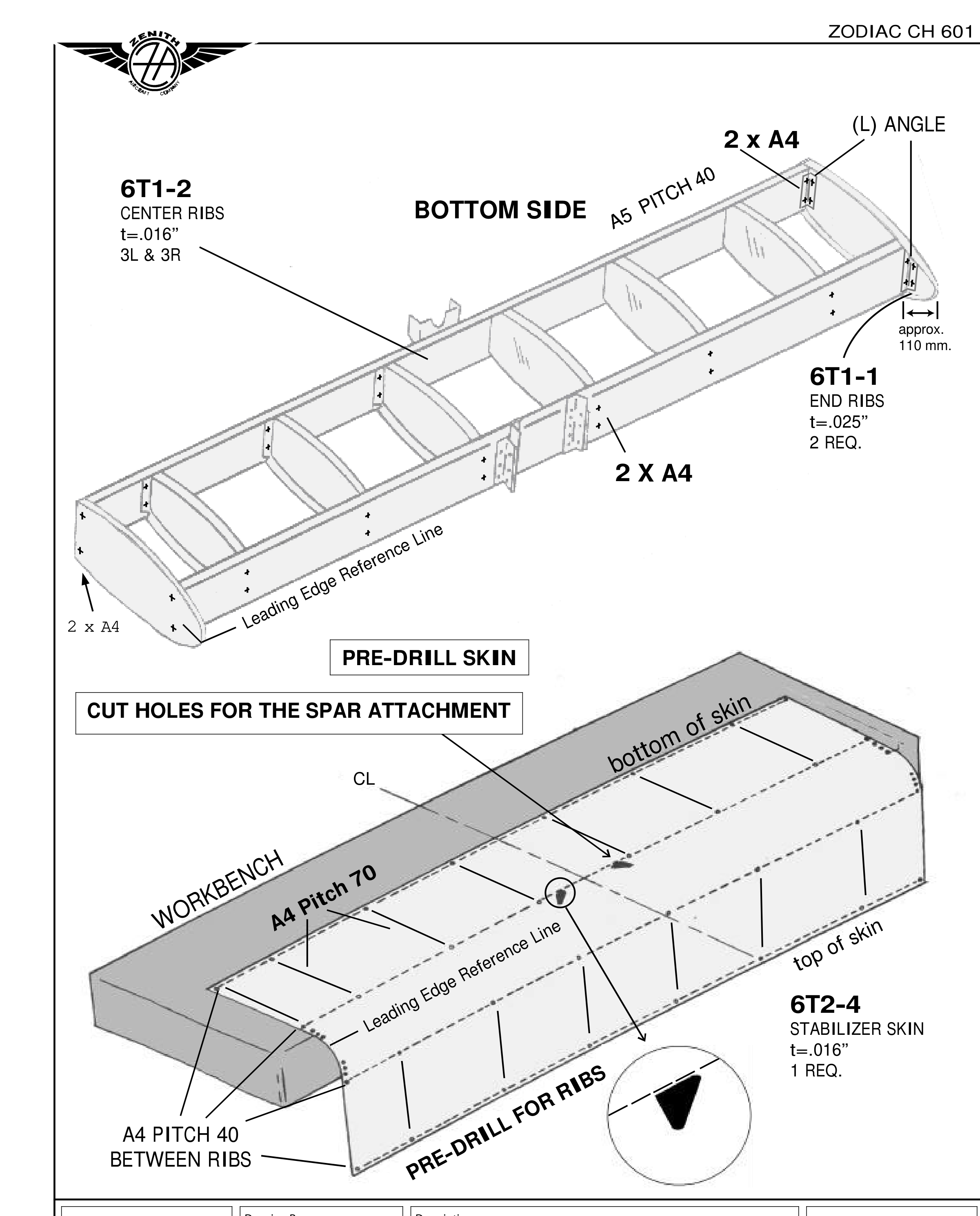
T-44: каркас, концевые L-профили и положение нижней обшивки 6T2-4. Вид показывает, какие отверстия под передние крепления находятся именно снизу.

Сначала ставят промежуточные нервюры, затем концевые. Положение концевых определяет обшивку: они заподлицо с задним краем верхней полки заднего Z-лонжерона. Нижняя сторона обшивки короче верхней; её задний край совмещается со стенкой заднего лонжерона.

Шаг 15. К торцам обоих лонжеронов подготавливают короткие L-профили для концевых нервюр 6T1-1. Профили стоят спереди стенок на двух A4 и входят внутрь нервюр. Длину подрезают по ширине стенки между касательными верхнего и нижнего гибов.

Шаг 16. Нервюры 6T1-2 по одной примеряют сначала к переднему, затем к заднему лонжерону. На внутренних передней и задней полках отмечают оси. Начинают со станции 160: нервюру центрируют между краями лонжерона, прижимают к усилителю, отверстие располагают посредине перекрытия полок. Перед сверлением освобождают пространство для патрона, сверлят, ставят Cleco, затем второе отверстие. Нервюру снимают и маркируют для повторения на остальных; задние станции переносят шаблоном.

В этом тексте указаны два A5 в пересечении с усилителями и два A4 в стенке между ними; сводка 05/2003 отдельно уточняет всего четыре заклёпки в полке лонжерона у каждой 6T1-2. Редакции различаются и не объявляются одной раскладкой.

Шаг 17. Нервюры соединяют Cleco с обоими лонжеронами. На станции 360 лонжероны сближаются на толщину усилителей.

Шаг 18. Концевые 6T1-1 ставят заподлицо с задним краем верхней полки заднего лонжерона. От передней стенки до передней точки нервюры примерно 110 мм. Через каждый L-профиль и стенку нервюры сверлят два отверстия №30.

Шаг 19. Каркас разбирают для снятия заусенцев, при выбранной технологии наносят антикоррозионное покрытие и собирают на заклёпках. В источнике как пример назван цинк-хроматный грунт; это название старой технологии, не назначение произвольной химии.

На T-44 обшивка и промежуточные нервюры подписаны .016 дюйма, концевые .025. Поздние концевые детали и обозначение 6T1-8 проверяют по своей редакции, а не заменяют автоматически номером 6T1-1 из этой главы.

Сверить с исходным текстом
ZENITH AIRCRAFT COMPANY Print Date: 10/24/01 ZODIAC CH 601 RIBS T-43 First Cleco the Center Ribs between the Front and Rear Spar, then add the End Ribs. The position of the End Ribs will determine the position of the Stabilizer Skin: the End Ribs are positioned flush with the aft edge of the top flange of the Rear Spar. Note: The bottom side of the Stabilizer Skin is shorter than the top side. — the bottom aft edge of the skin is flush with the Spar web, the middle diagram on drawing 6T2 shows the Stabilizer skin and the Rear Spar, (also called the Rear “Z”!). Cut the two holes for the Attachment Doublers in the bottom side of the Stabilizer Skin. 15. Prepare the Front and Rear Spar by installing the short length of L Angles at each end of the spars to attach the End Ribs 6T1-1. LAYOUT: The L Angles are Riveted on the front side of the Spars with 2 A4 rivets into the Spar web. NOTE: The L angle will rivet inside the End Rib – cut the length of the L angles to the width of the spar web (distance between the upper and lower bent tangent line). 16. Cleco the Center Ribs 6T1-2 one at a time first to the Front Spar then to the Rear Spar. MARK: the flange center line on the inside for the front and rear flange. CENTER: Start with rib at station 160, center the Rib on the Spar between the top and bottom flange by holding the rib between your thumb and forefinger to feel the rib flush with the edges. Clamp in place with one clamp on the Doubler. The rivet hole is on the split middle of the overlap of the rib flange with the Doubler. Before drilling, use your finger to push the rib clear of the chuck; drill through the flange into the doubler and spar. Cleco and drill the second hole. Remove and label the rib to repeat the procedure on the remaining Ribs. Layout the rib stations on the Rear Spar using the rib position template to drill the ribs. RIVETS: 2A5 at the intersection with the Doublers. 2A4 in the Spar Web between the doublers, see drawing 6T2 bottom left diagram. 17. Cleco the Ribs to the Front and Rear Spars. NOTE: At rib station 360 the spars are drawn together by the thickness of the doublers 18. Position the End Ribs 6T1-1 flush with the aft edge of the top flange of the Rear Spar. CHECK: The distance from the Front Spar (web) to the front of the End Rib is approximately 110mm. DRILL: Two holes #30 in each L Angles and the Rib web. 19. Deburr, apply the corrosion inhibitor (zinc chromate primer) if desired, and rivet the skeleton together.

Страница 14 исходного PDF

Нижняя обшивка и устранение крутки
Нижняя обшивка и устранение крутки · исходный лист 15
Нижняя обшивка и устранение крутки · исходный лист 15 · Открыть крупно

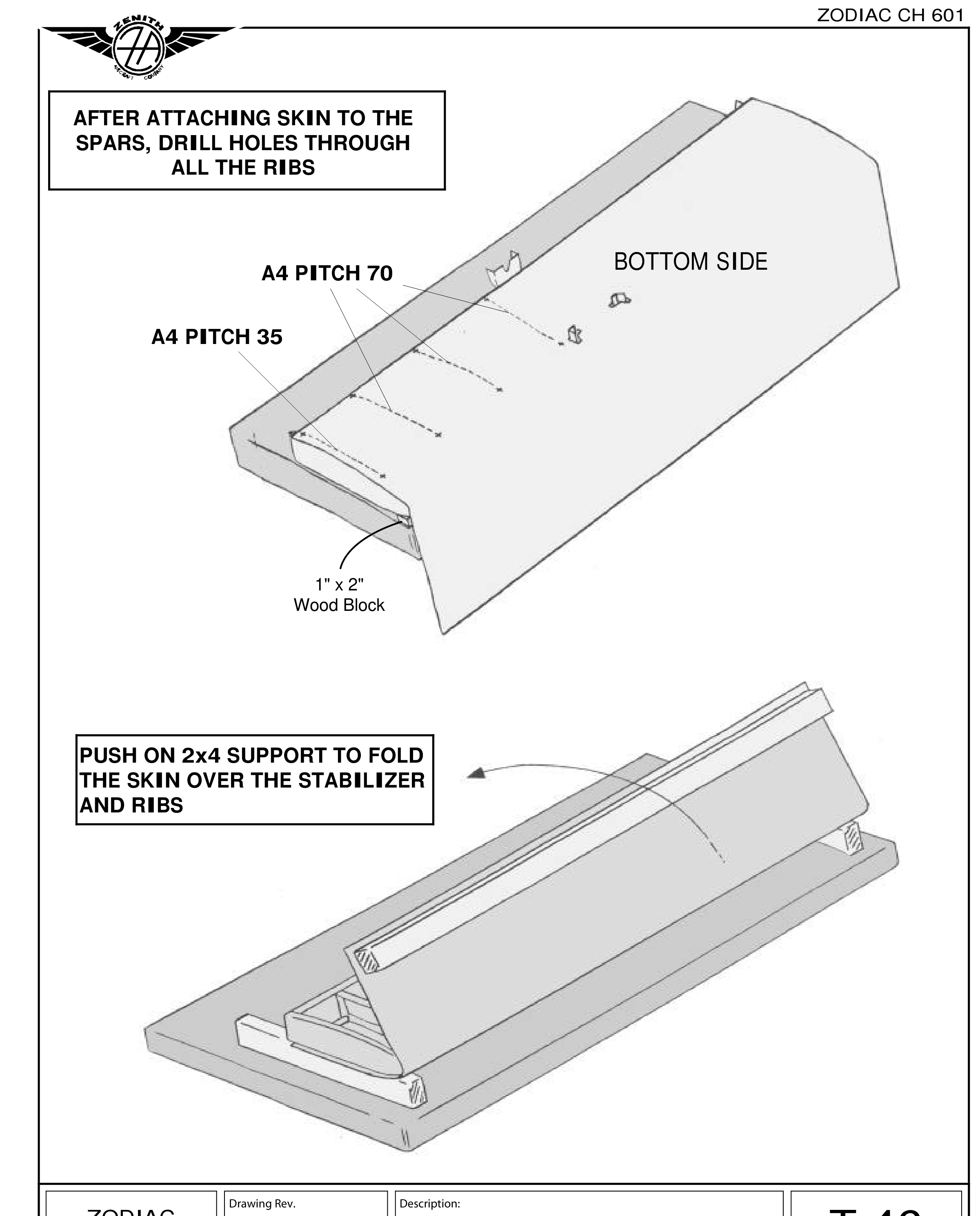
T-46: начальная нижняя сторона на брусках и поддержка при заворачивании обшивки. На разных рядах рисунка — разные шаги A4; размеры берут у соответствующей выноски.

Шаг 20. Обшивку перемещают, взяв за задний край с широко расставленными руками для равномерной поддержки. При работе вдвоём каждый удерживает свою часть; тонкий лист нельзя перегибать локальным захватом.

Шаг 21. Нижнюю сторону определяют сравнением расстояния от заднего края до середины радиуса носка с такой же базой на нервюре от стенки лонжерона. Низ короче примерно на 3/4 дюйма. Снизу отмечают ось и вырезы под передние крепления 6T2-1; сначала сверлят три разгрузочных отверстия 1/4 дюйма, затем соединяют их резом или круглым напильником.

Шаг 22. Шаблоном отмечают оси нервюр, переднего и заднего лонжеронов, раскладывают шаг заклёпок и сверлят пилотные №40.

Шаг 23. Каркас располагают перевёрнутым, обшивку — со свесом за край стола; крепления выходят через вырезы. Задний край временно фиксируют лентой заподлицо с задней кромкой стенки лонжерона. Под концевые нервюры подкладывают бруски 1 × 2 дюйма, устраняя крутку. Проверяют носовую линию гиба у концевых нервюр. Начинают от середины и поочерёдно сверлят левую/правую стороны к концам по заднему лонжерону, затем нервюры и передний лонжерон. Заклёпки A4 ставят головкой на обшивку .016 дюйма.

Шаг 24. Сборку переворачивают и подкладывают под концевые нервюры бруски 1 × 2 дюйма, чтобы крепления не опирались на стол. Ремни проводят под столом и поверх стабилизатора. На T-46 отдельно подписаны A4 с шагом 35 и 70 мм на разных рядах; эти подписи не заменяют шаги верхней стороны из T-47.

Сверить с исходным текстом
ZENITH AIRCRAFT COMPANY Print Date: 10/24/01 ZODIAC CH 601 SKIN BOTTOM SIDE T-45 Fit the bottom side of the Stabilizer Skin first. Work with skeleton upside down with the skin overhanging down over the side of the work bench. Reference the Skin along the aft edge of the Spar checking the center line of the bent leading edge radius against the Rib. Level the assembly by blocking under the End Ribs and start drilling from the center out along the Rear Spar. Drill the Ribs and the Front Spar starting at the center and moving out towards the ends. Rivet the bottom side before starting on the top side. 20. HANDLE THE SKIN WITH CARE: The best way to move the Skin is to grab hold of the Skin between your fingers along the rear edge (top side or bottom is immaterial). Keep your arms well separated to help support the Skin evenly. The same technique is used when two people move the Skin; however one persons can handle the Stabilizer Skin very effectively. 21. Identify the bottom side of the formed Stabilizer Skin. Confirm by measuring the distance between the aft edge of the skin to the middle of the bent radius of the leading edge of the Skin against the same measure on the Rib (remember to measure from the spar web), the bottom side is shorter by approximately ¾” CUTOUT for the front Attachment Doublers: Mark the aircraft center line and the position of the cut-out to clear the two Front Spar Attachments 6T2-1 on the bottom side. Drill 3 corner relief holes (1/4”) and cut in-between or use a round rat tail file to connect the holes! 22. Use the Rib positioning template to mark the rib center line on the skin, and mark the front and rear spar center line on the skin. Layout the rivet pitch and drill pilot with #40 drill bit. 23. Position the Skin over the skeleton with the Attachment brackets through the cutouts. Duct tape the rear edge to the Spar web to hold the Skin flush with the aft edge of the Spar. LEVEL: Slide 1×2” blocks under the End Ribs to remove any twist in the flexible skeleton. CHECK: The position of the center line of the leading edge bend radius against the End Ribs. DRILL & CLECO: A4, start at the center and back drill into the Rear Spar alternating between the left and right side working your way to the tips. Work your way up the Ribs and start drilling the Front Spar starting at the center working towards the tips. RIVET: With A4, rivet head on the .016 Skin. 24. Turn the assembly over and slide a 1”x2” board underneath the End Ribs to clear the Attachment brackets above the work bend. STRAPPING: Run the strap underneath the workbench and over the Stabilizer assembly. Ratchet type straps are easy to adjust and can be set up ahead of time.

Страница 16 исходного PDF

Верхняя обшивка, петля и законцовки
Верхняя обшивка, петля и законцовки · исходный лист 17
Верхняя обшивка, петля и законцовки · исходный лист 17 · Открыть крупно

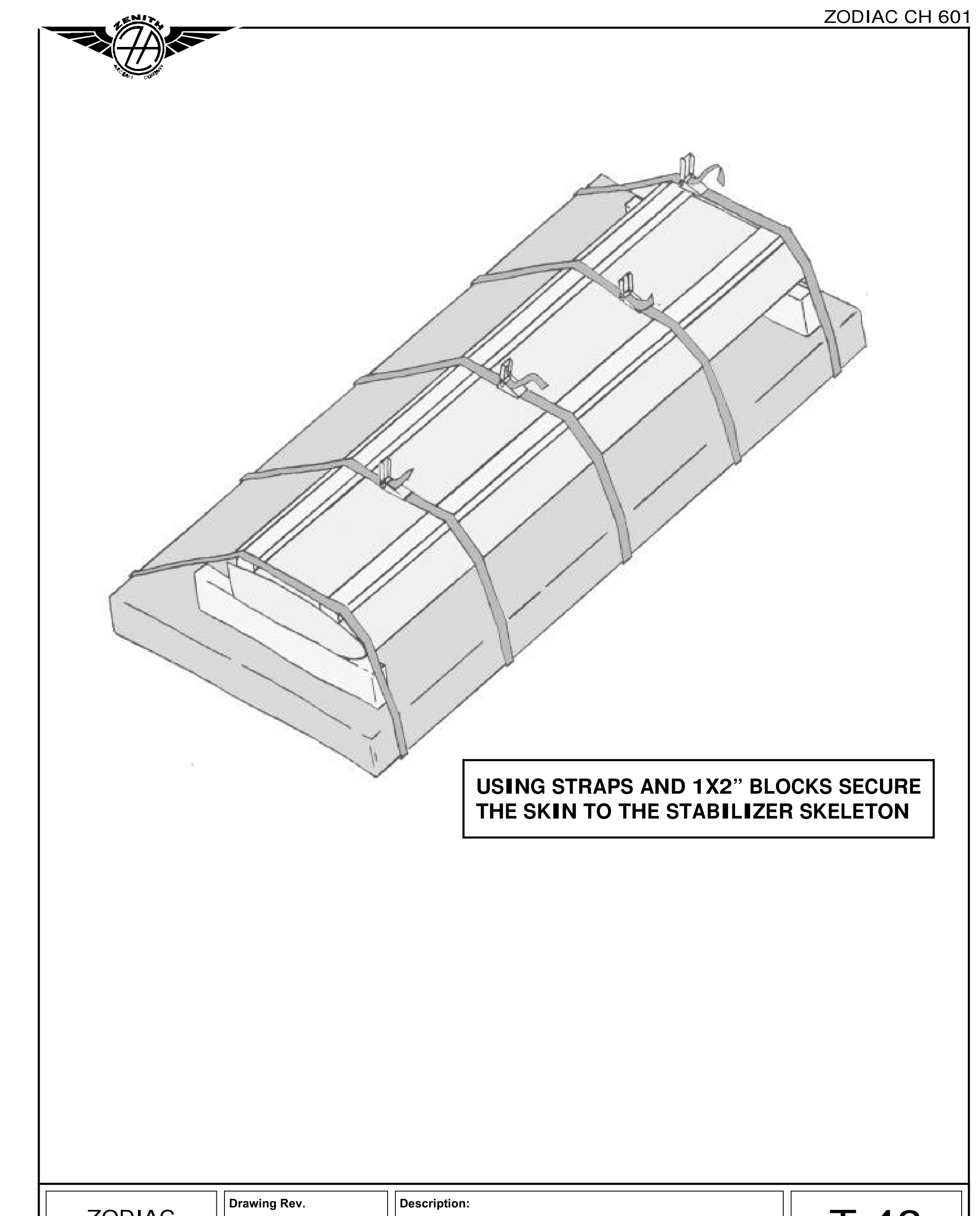
T-48: ремни и распределяющие нагрузку бруски удерживают верхнюю обшивку без крутки. Рисунок не задаёт усилие затяжки ремней.

Шаг 25. Верх обшивки осторожно заворачивают на каркас с поддержкой длинным бруском; во вводной строке назван 1 × 2 дюйма, в самом шаге — 2 × 4 дюйма длиной 8 футов. Второй брусок 1 × 2 кладут под ремни перед передним лонжероном. Ремни затягивают постепенно до ровного прилегания; шести достаточно по тексту. Подкладками у передней части концевых нервюр устраняют крутку и проверяют уровнем оба конца.

Шаг 26. Размечают передний и задний ряды, шаблоном — нервюры. Указаны A4: шаг 40 мм через передний лонжерон и 60 мм по нервюрам. Пилотные отверстия №40.

Шаг 27. Рояльную петлю длиной 6 футов (1830 мм в исходнике) центрируют по оси между обшивкой и задним лонжероном. Крайние отверстия — в 10 мм от концов петли. Сверление №30, крепление A4 через задний лонжерон и петлю.

Шаг 28. Стеклопластиковые законцовки вводят внутрь обшивки. Ряд размечают в 10 мм от края обшивки, повторяя шаг концевой нервюры. Сверлят №30 и ставят Cleco.

Шаг 29. В заднюю часть каждой стеклопластиковой законцовки ставят замыкающую нервюру; сверление №30 с шагом 40 мм и Cleco. Шаг 30. Законцовки заклёпывают A4.

По сводке 05/2003 для петли отдельно указан коррозионностойкий стальной штырь; для законцовок — A4 с шагом 40 к 6T1-8/6T2-4, а в концевой нервюре есть отдельное уточнение A4 с шагом 35, 13 штук и три перед лонжероном. Здесь сохранены старые операции, а поздняя раскладка требует применимого листа.

Сверить с исходным текстом
ZENITH AIRCRAFT COMPANY Print Date: 10/24/01 ZODIAC CH 601 SKIN TOP SIDE T-47 Handle the Skin with care, use a 1”x2” 8 ft. long to help support the Skin when folding the top side of the Skin over the ribs. Slide another 1×2” underneath the straps just ahead of the Front Spar to gently support the Skin. Slowly tighten the straps until the Skin lays flat. 25. Use straps to hold the Top side of the Skin on the Skeleton. HANDLING: To push the Skin down on the skeleton, take hold of an 8 foot 2”x4” along the sides, hold it up against the Skin and gently lower the Skin down. Partially tighten the straps. Add another 1×2 just in front of the Front Spar for added support. 6 straps is more than adequate! LEVEL: Block the front of the End Ribs to eliminate twist. Use a level to check both ends. 26. Mark the rivet lines for the front and rear Spar. Use the rib positioning Template to layout the position of the Ribs. RIVETS +PITCH: a) A4 pitch 40 through the Front Spar. b) A4 pitch 60 through the Ribs. c) Drill #40 Pilot holes. 27. Clamp the 6 ft (1830mm) Piano Hinge between the Skin and the Rear Spar, centered on aircraft center line. RIVETS + PITCH: A4 through the Rear Spar and Piano Hinge. (Locate the end holes at 10mm from the end of the Hinge). DRILL: #30 RIVET: A4 28. Add the Fiberglass tips inside the skin. PITCH: Draw a line at 10mm from the end of the Skin and duplicate the rivet pitch in the End Rib by sighting across. DRILL & CLECO: #30 The Skin to the Fiberglass Tip. 29. Add the Tip Rib inside the rear ends of the Fiberglass Tips. DRILL + CLECOS: #30 Pitch 40 30. Rivet the tips with A4. 10/24/01: ZAC Engineering/601 manual/stab-TAIL1.doc

Страница 18 исходного PDF

Подробности стеклопластиковых законцовок
Подробности стеклопластиковых законцовок · исходный лист 18
Подробности стеклопластиковых законцовок · исходный лист 18 · Открыть крупно

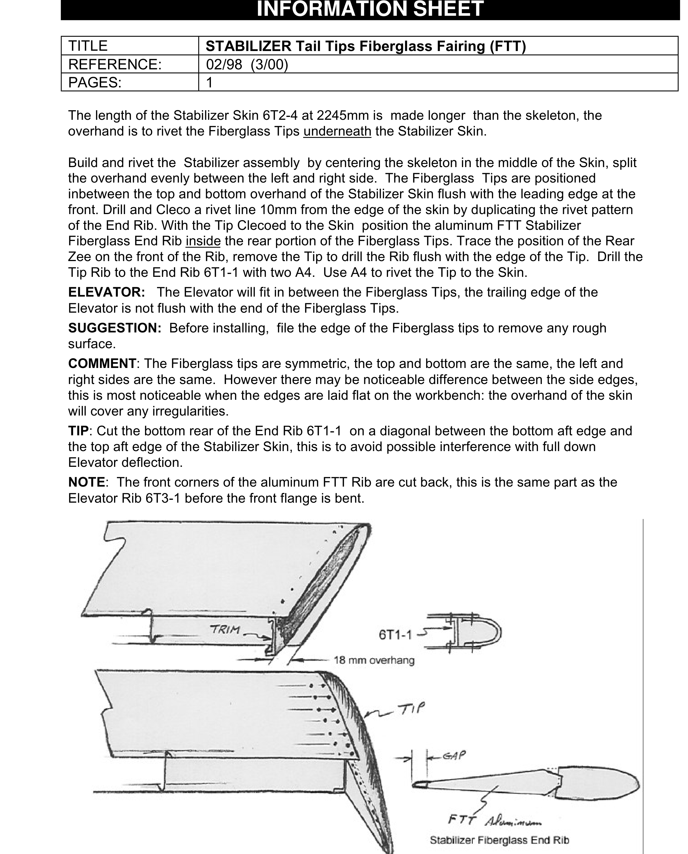
Информационный лист FTT: перекрытие обшивки, место замыкающей нервюры, подрезка заднего угла и отдельная заготовка алюминиевой нервюры. Ненумерованное дополнение не посчитано дополнительными шагами 31 и далее.

Дополнение FTT, маркировка «02/98 (3/00)» — февраль 1998, март 2000. Обшивка 6T2-4 длиной 2245 мм длиннее каркаса для крепления законцовок изнутри. Каркас центрируют, свес делят поровну слева и справа. Законцовку ставят между верхним и нижним свесами заподлицо с передней кромкой.

Ряд в 10 мм от края обшивки повторяет раскладку концевой нервюры. При законцовке на Cleco в заднюю часть вставляют алюминиевую FTT-нервюру, отмечают на ней положение заднего Z-профиля, снимают законцовку и сверлят нервюру заподлицо с её краем. FTT-нервюра соединяется с концевой 6T1-1 двумя A4; законцовка с обшивкой — A4.

Руль высоты входит между законцовками; его задняя кромка не обязана быть заподлицо с их торцами. Кромки стеклопластика до установки доводят, убирая неровности. Законцовки симметричны по верху/низу и слева/справа, но края могут немного различаться — их перекрывает свес обшивки.

Нижний задний угол 6T1-1 подрезают по диагонали между нижним задним краем и верхним задним краем обшивки против контакта при полном отклонении руля вниз. Передние углы алюминиевой FTT-нервюры срезаны; в этой редакции она соответствует заготовке 6T3-1 до гиба передней полки. На рисунке отмечен свес 18 мм — его не переносят как новый размер вместо фактического центрирования и редакционного листа.

Сверить с исходным текстом
INFORMATION SHEET TITLE STABILIZER Tail Tips Fiberglass Fairing (FTT) REFERENCE: 02/98 (3/00) PAGES: 1 The length of the Stabilizer Skin 6T2-4 at 2245mm is made longer than the skeleton, the overhand is to rivet the Fiberglass Tips underneath the Stabilizer Skin. Build and rivet the Stabilizer assembly by centering the skeleton in the middle of the Skin, split the overhand evenly between the left and right side. The Fiberglass Tips are positioned inbetween the top and bottom overhand of the Stabilizer Skin flush with the leading edge at the front. Drill and Cleco a rivet line 10mm from the edge of the skin by duplicating the rivet pattern of the End Rib. With the Tip Clecoed to the Skin position the aluminum FTT Stabilizer Fiberglass End Rib inside the rear portion of the Fiberglass Tips. Trace the position of the Rear Zee on the front of the Rib, remove the Tip to drill the Rib flush with the edge of the Tip. Drill the Tip Rib to the End Rib 6T1-1 with two A4. Use A4 to rivet the Tip to the Skin. ELEVATOR: The Elevator will fit in between the Fiberglass Tips, the trailing edge of the Elevator is not flush with the end of the Fiberglass Tips. SUGGESTION: Before installing, file the edge of the Fiberglass tips to remove any rough surface. COMMENT: The Fiberglass tips are symmetric, the top and bottom are the same, the left and right sides are the same. However there may be noticeable difference between the side edges, this is most noticeable when the edges are laid flat on the workbench: the overhand of the skin will cover any irregularities. TIP: Cut the bottom rear of the End Rib 6T1-1 on a diagonal between the bottom aft edge and the top aft edge of the Stabilizer Skin, this is to avoid possible interference with full down Elevator deflection. NOTE: The front corners of the aluminum FTT Rib are cut back, this is the same part as the Elevator Rib 6T3-1 before the front flange is bent.

Корзина

0
image/svg+xml

No products in the cart.

Continue Shopping