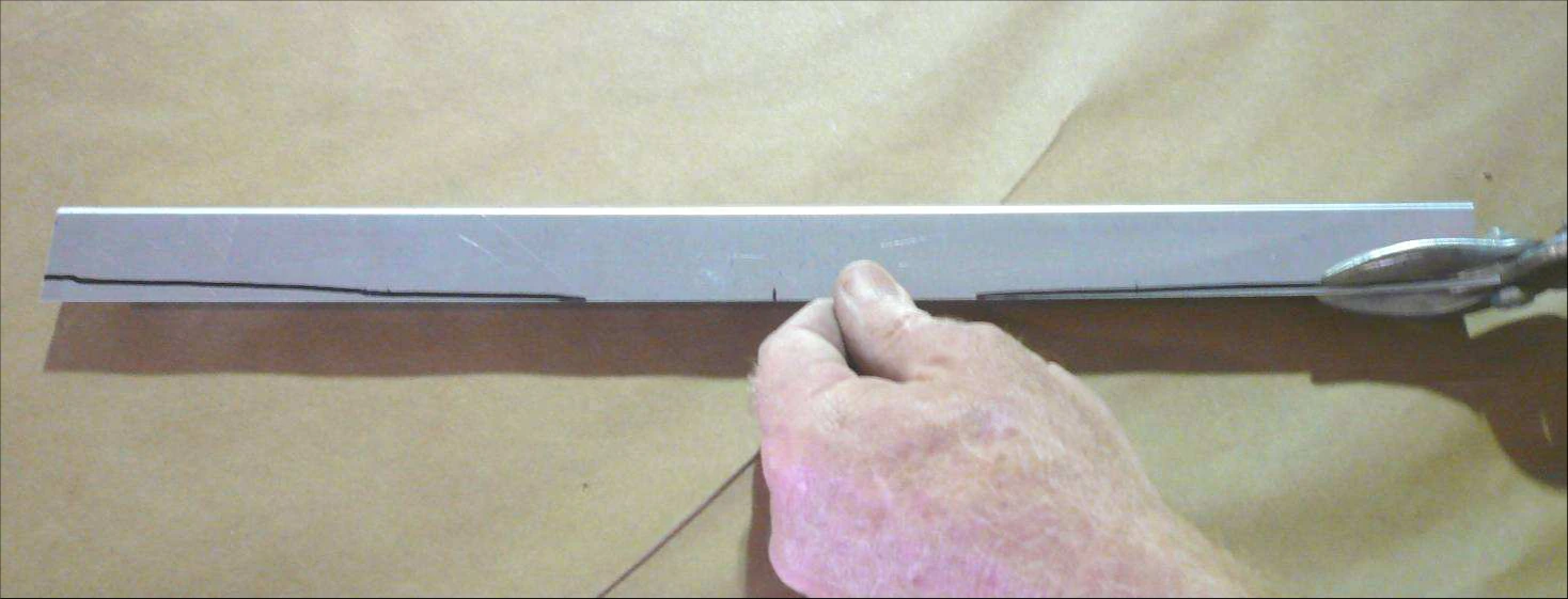
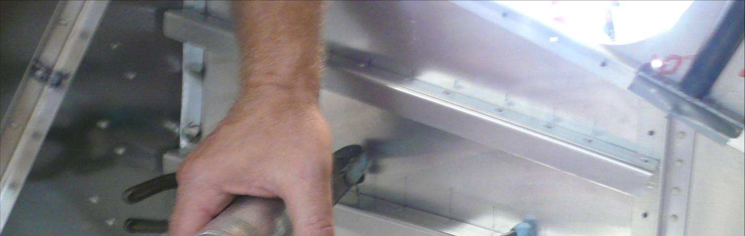
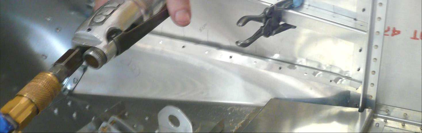
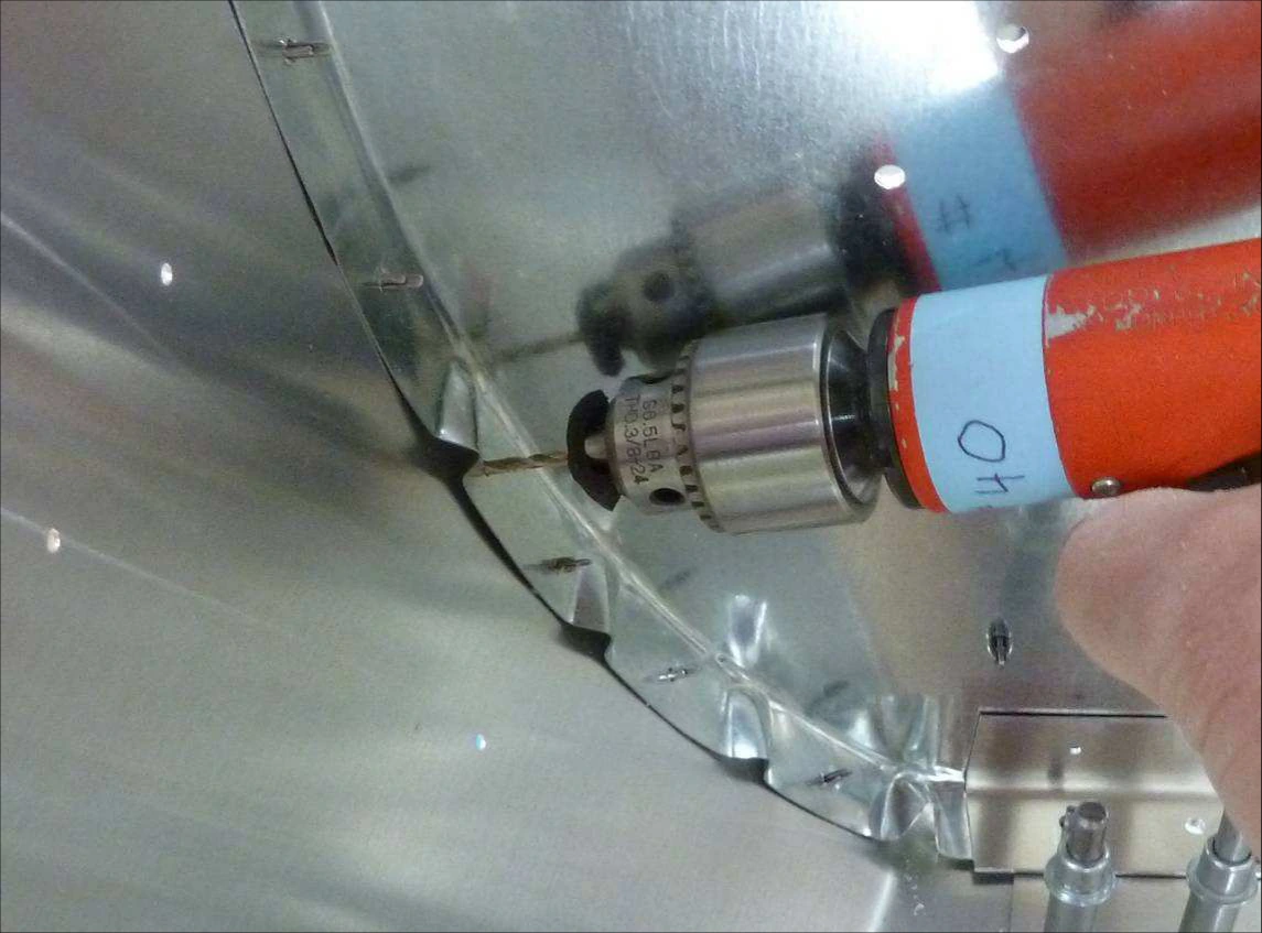
c75-fa-6-c75-fa-7-joining-fuselage · 1.0 (12 /21/2015)). Руководство CH 750 Cruzer из местного комплекта. Не подменяет применимые чертежи и их обновления. Детали и размеры версий STOL и SD в этот раздел не переносятся.
Разделы C75-FA-6 и C75-FA-7: соединение задней и передней частей из деталей с согласованными отверстиями.
Фотоинструкция дополняет чертежи и уступает им при расхождении. Технологические нормы и допуски — по применимым Construction Standards for Zenair Light Aircraft.
Сверить с исходным текстом
CRUZER
Zenith Aircraft Company
Fuselage Joining & Forward Fuselage
Section C75-FA-6 & C75-FA-7, Page 1 of 1
Revision 1.0 (12 /21/2015))
Section C75-FA-6 & C75-FA-7
Fuselage Joining &
Forward Fuselage
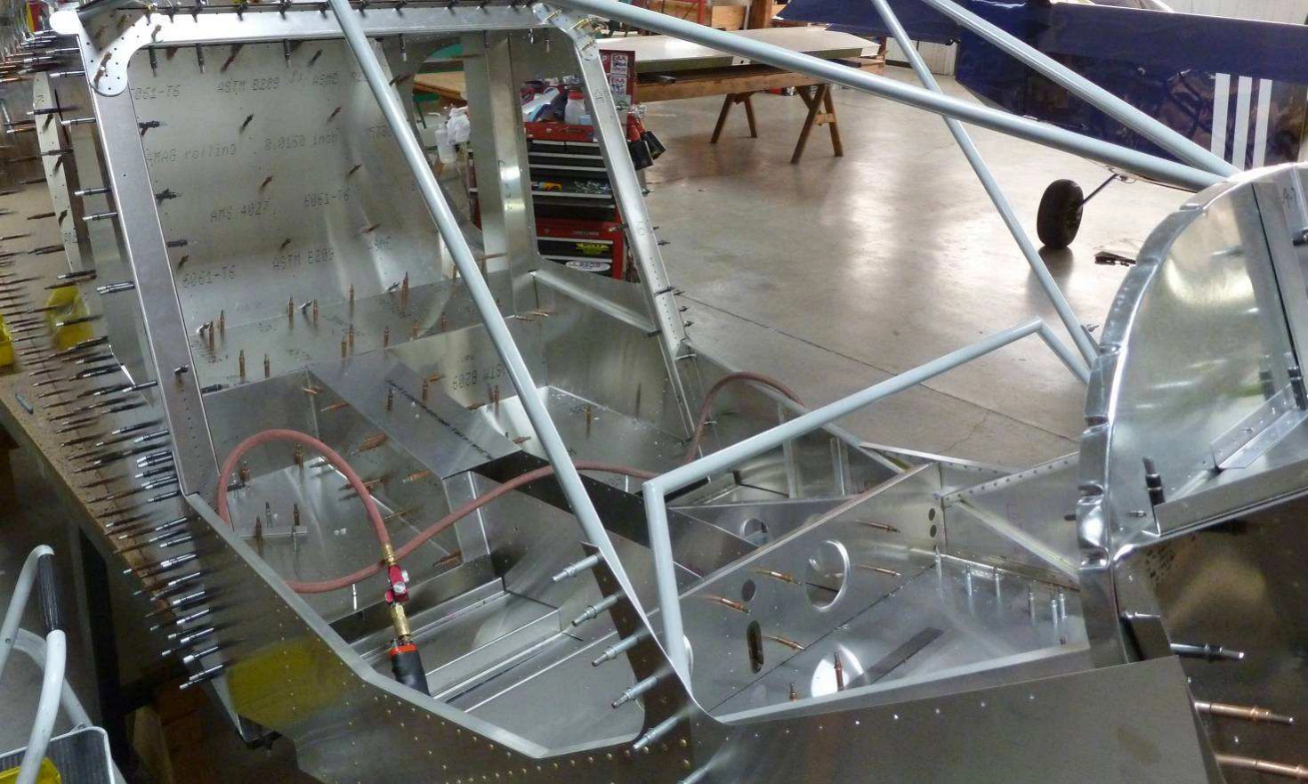
This manual has been prepared for assembly of the fuselage supplied with match drilled parts.
This photo assembly manual is intended as a supplement to the drawings. If there is any
discrepancy between this manual and the drawings, the drawings supersede this manual. For
more information on building standards and allowable tolerances see “Construction Standards
for Zenair Light Aircraft” available from Zenith Aircraft Co.
CH 750 Cruzer · Соединение частей фюзеляжа · Страница 2 из 21
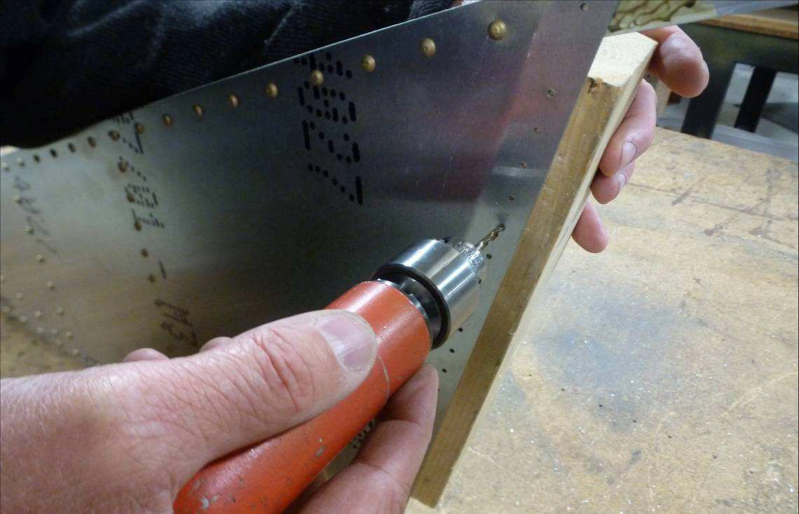
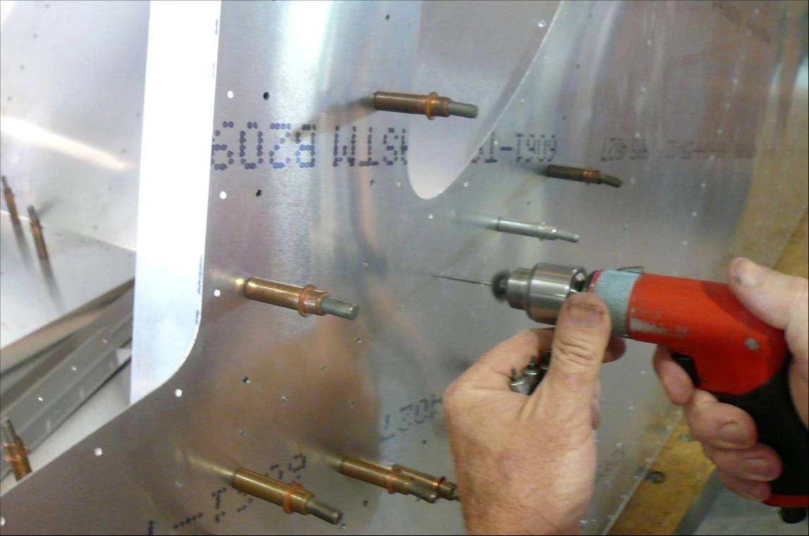
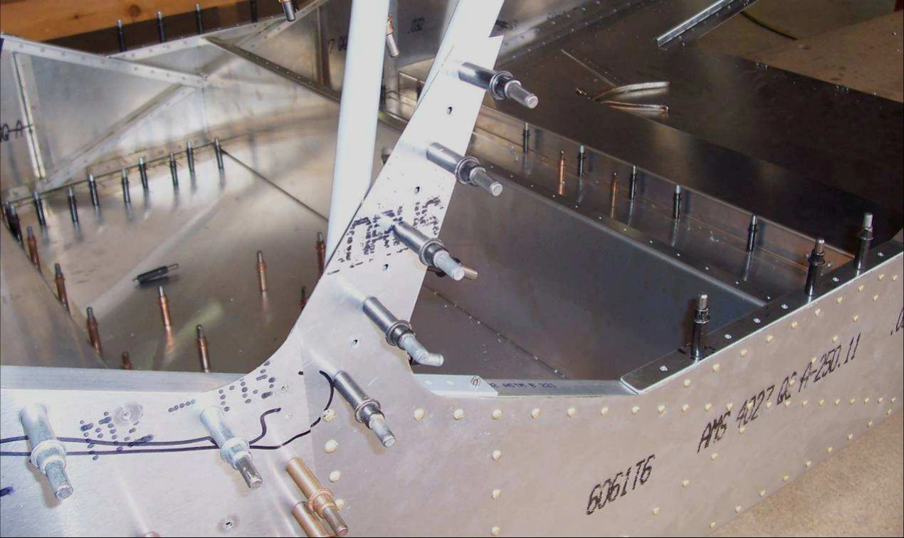
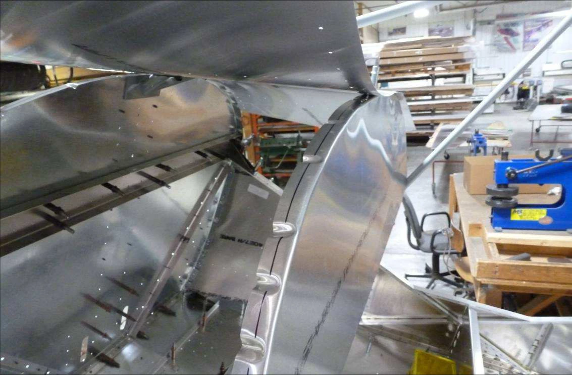
Увеличьте отверстия задней кромки борта кабины #30, поддерживая лист деревянным бруском, затем #20.
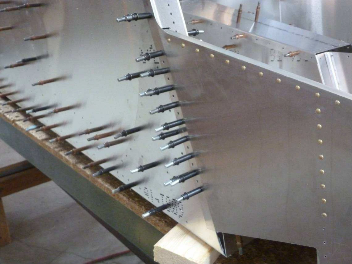
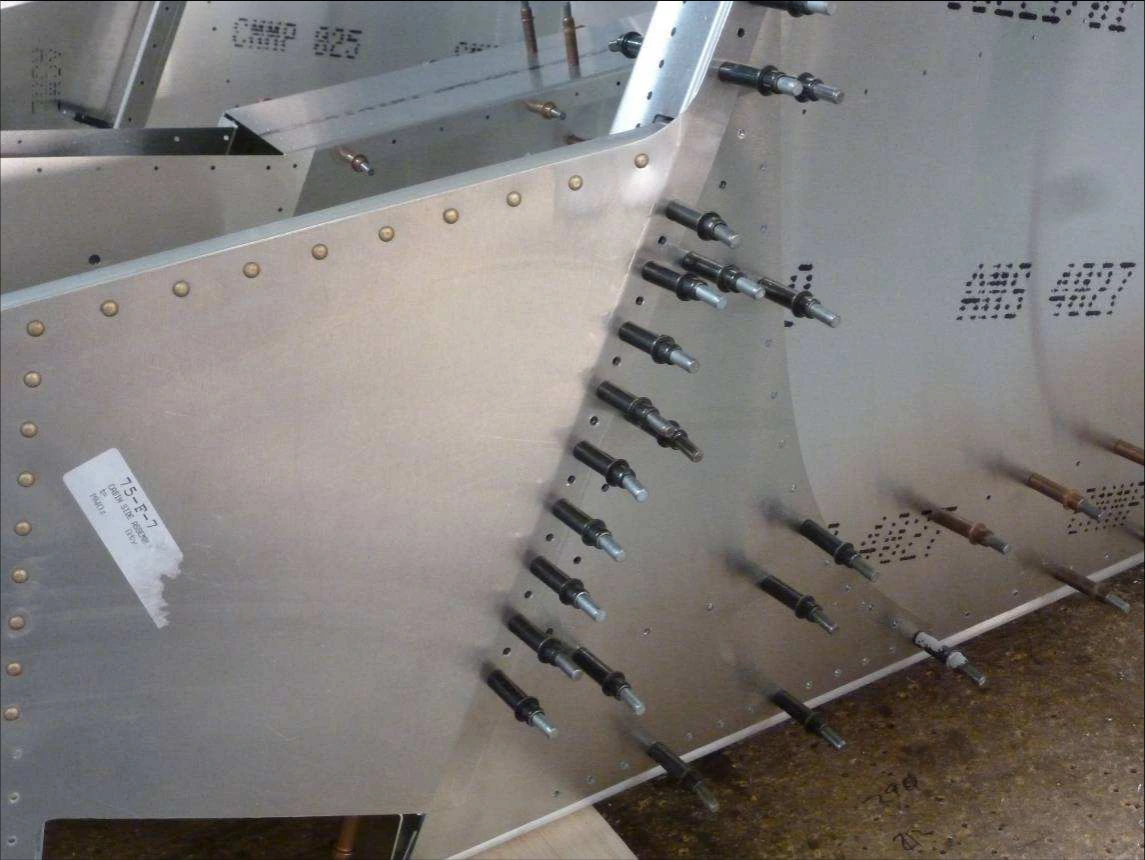
Заведите лонжероны в вырезы боковых профилей и кожухов управления флаперонами. Соедините борт кабины с боковой обшивкой и боковым профилем на Cleco; профиль шасси — с нижней обшивкой.
Переднюю часть поддержите отдельной подставкой, принимающей её вес.
Сверить с исходным текстом
CRUZER
Zenith Aircraft Company
Fuselage Joining & Forward Fuselage
Section C75-FA-6 & C75-FA-7, Page 2 of 2
Revision 1.0 (12 /21/2015))
Expand the holes on the aft edge in the Cabin Side with a #30 drill bit. Use a block of wood to support the
Cabin Side while drilling. Then expand the holes with a #20 drill bit.
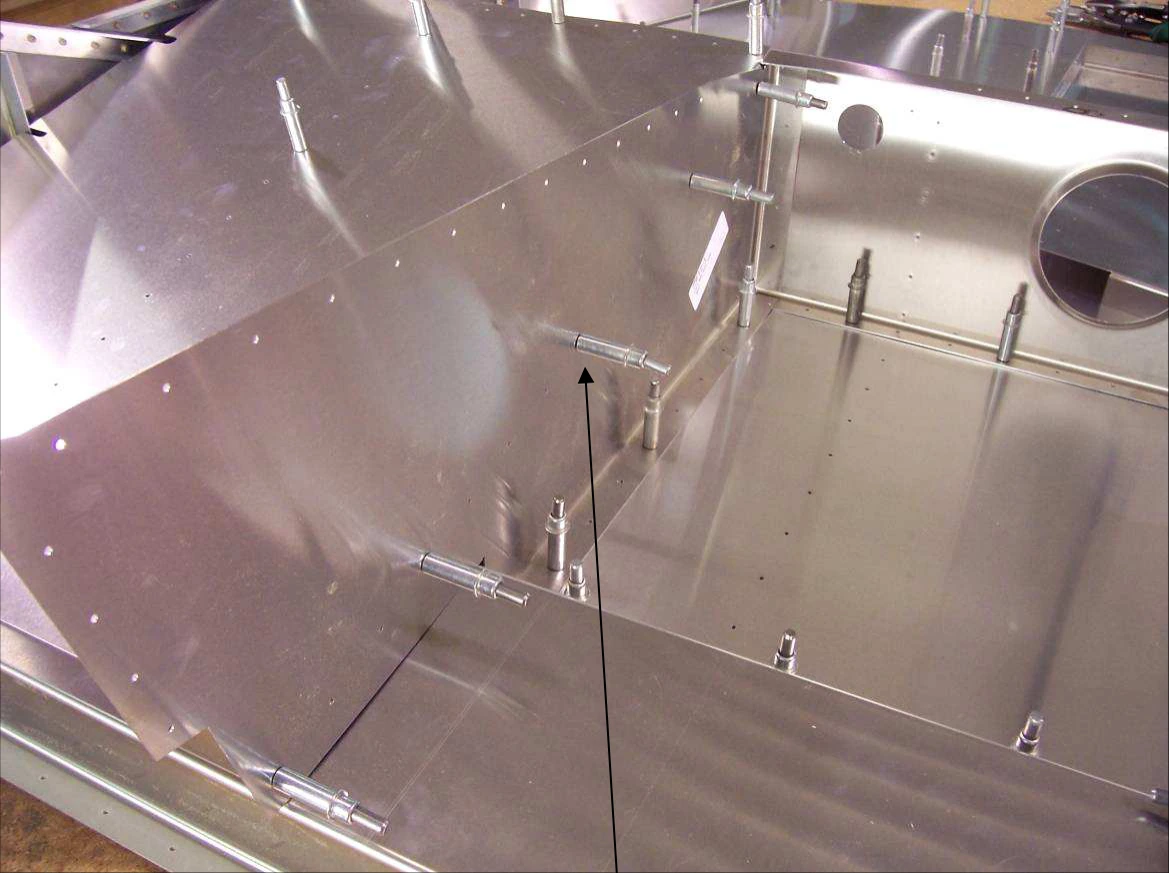
Slide the Longerons inside of the cutouts on the Side Channels and Flaperon Control Covers. Cleco the
Cabin Side to the Side Skin and Side Channel. Cleco the Gear Channel to the Bottom Skin. Use a stand
under the front end of the Forward Fuselage to support its weight.
CH 750 Cruzer · Соединение частей фюзеляжа · Страница 3 из 21
Через боковой лист просверлите лонжерон борта кабины #40 и поставьте Cleco. Увеличьте отверстия #20.
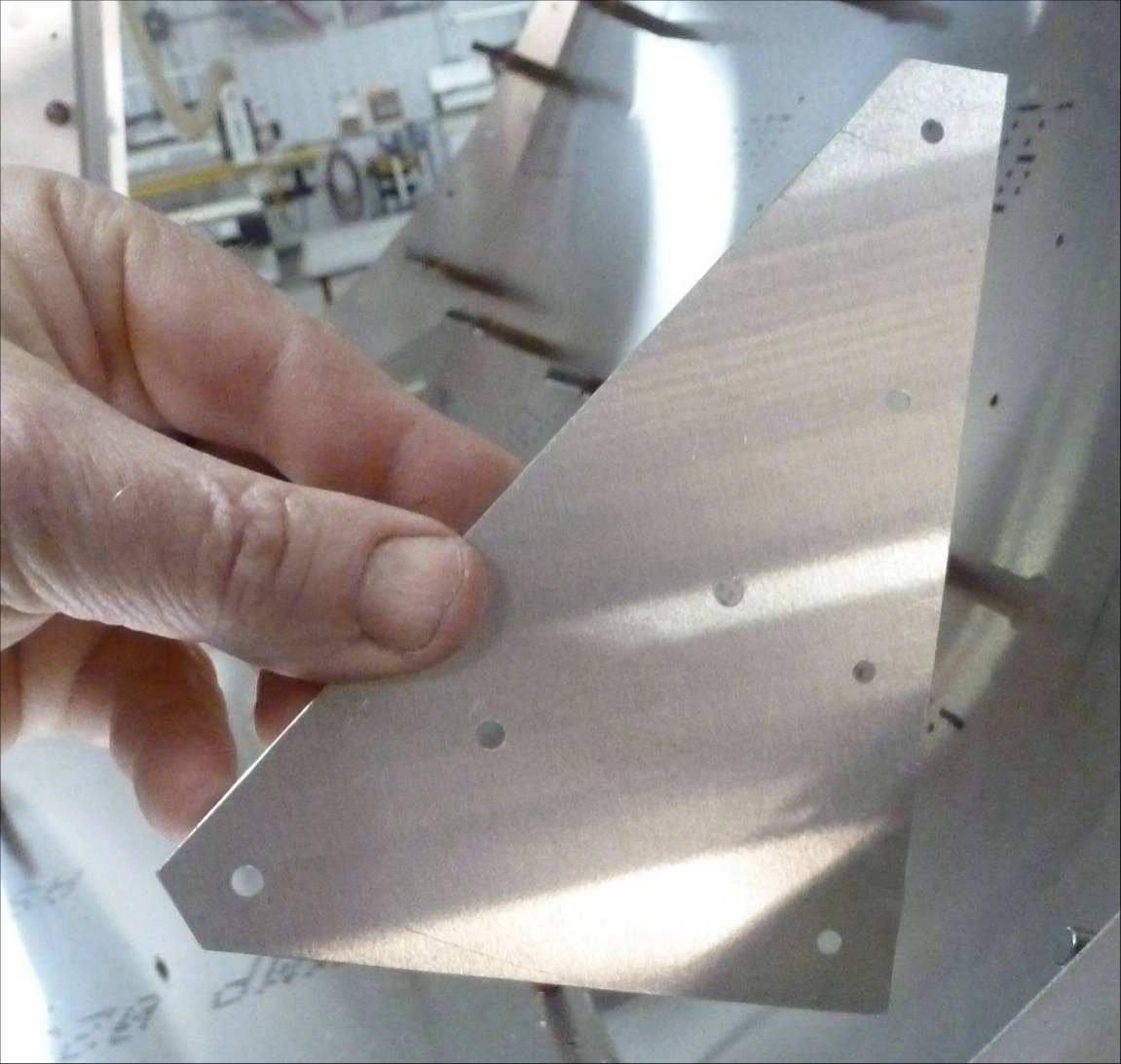
Соедините косынку C75F4-7 с боковым листом и бортом кабины на Cleco. Её отверстия увеличьте #20.
Сверить с исходным текстом
CRUZER
Zenith Aircraft Company
Fuselage Joining & Forward Fuselage
Section C75-FA-6 & C75-FA-7, Page 3 of 3
Revision 1.0 (12 /21/2015))
With a #40 drill bit, back drill through the Side Skin into the Longeron on the Cabin Side and Cleco. Use a
#20 drill bit to expand the holes and Cleco.
Cleco the Side Skin Gusset to the Side Skin and Cabin Side. With a #20 drill bit,
expand the holes in the Side Skin Gusset and Cleco.
P/N: C75F4-7
Side Skin Gusset
CH 750 Cruzer · Соединение частей фюзеляжа · Страница 4 из 21
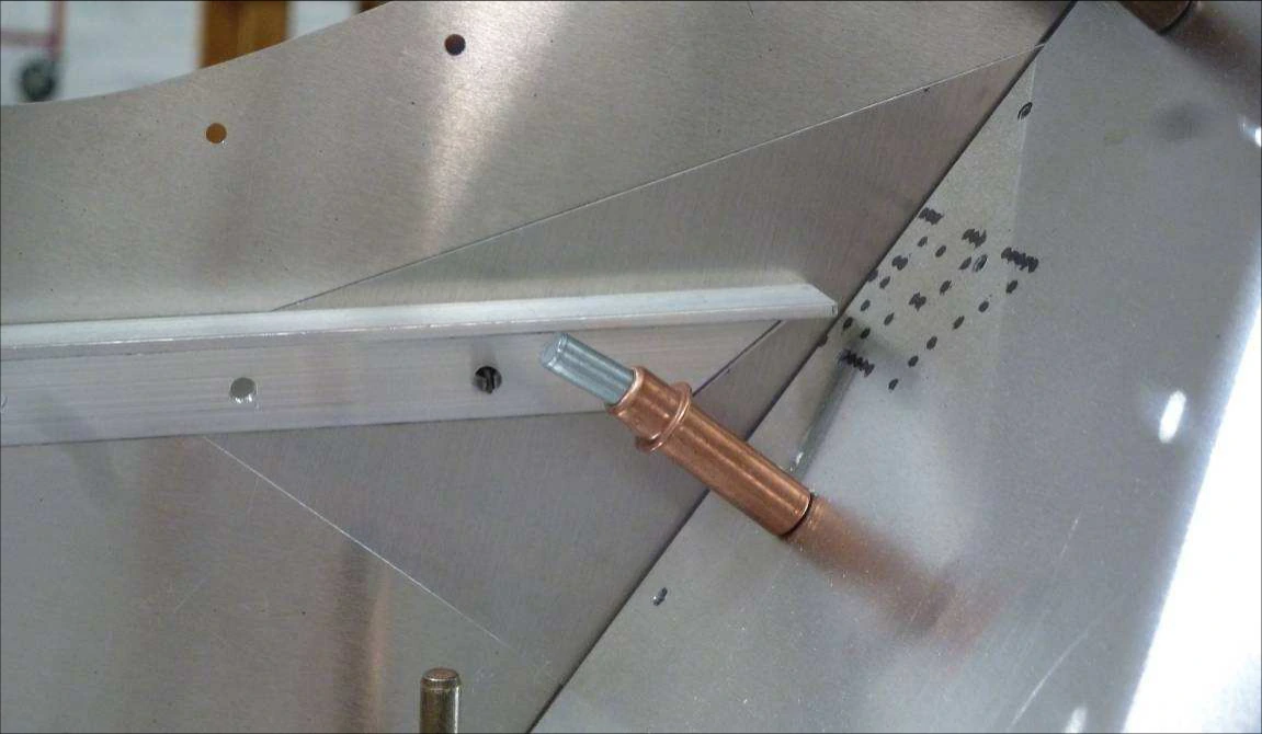
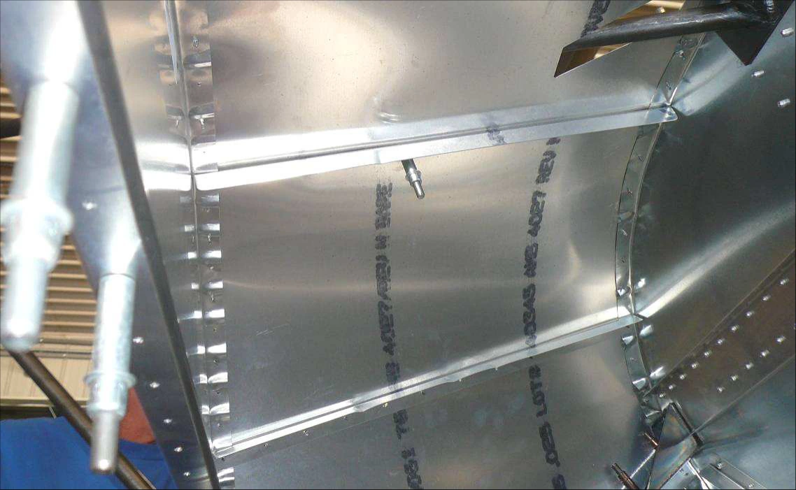
Заведите косынку C75F4-9 между лонжероном, профилем задней стенки багажника и боковой обшивкой.
Установите Cleco по показанному сопряжению.
Сверить с исходным текстом
CRUZER
Zenith Aircraft Company
Fuselage Joining & Forward Fuselage
Section C75-FA-6 & C75-FA-7, Page 4 of 4
Revision 1.0 (12 /21/2015))
P/N: C75F4-9
Longeron Gusset
Slide the Longeron Gusset between the Longeron, Baggage Back Channel, and the Side Skin and cleco.
CH 750 Cruzer · Соединение частей фюзеляжа · Страница 5 из 21
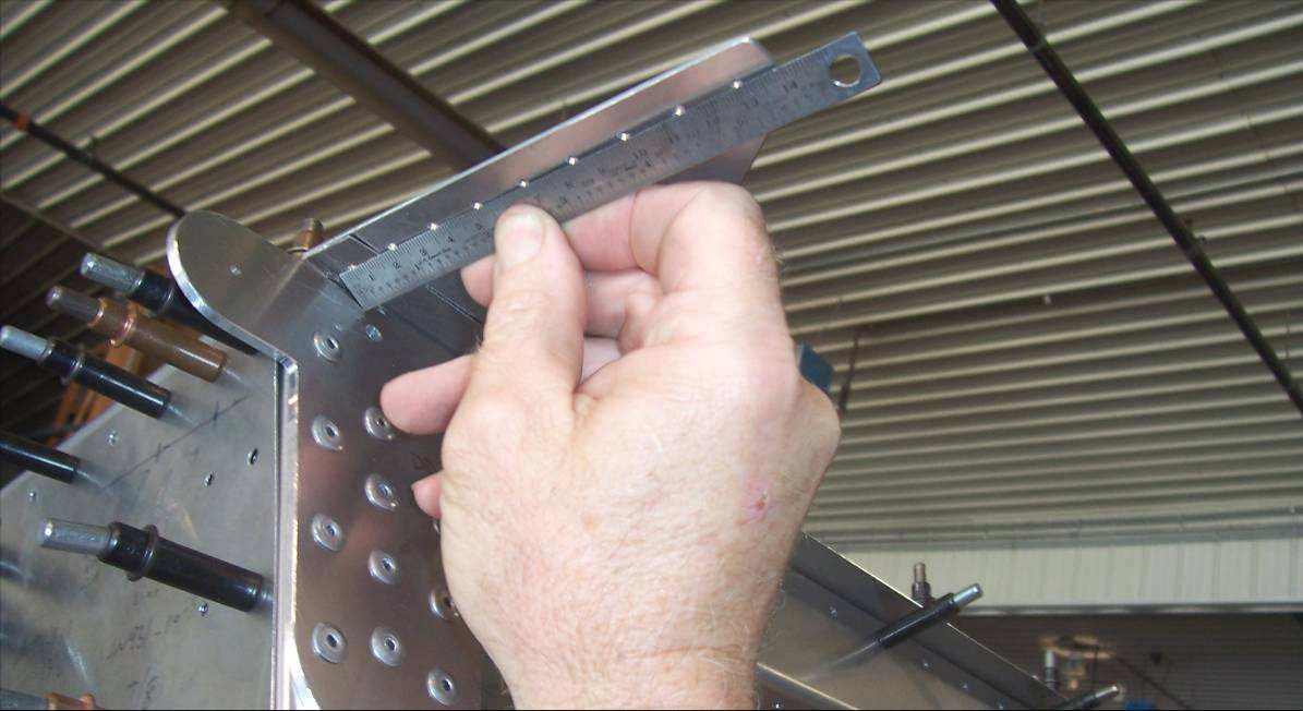
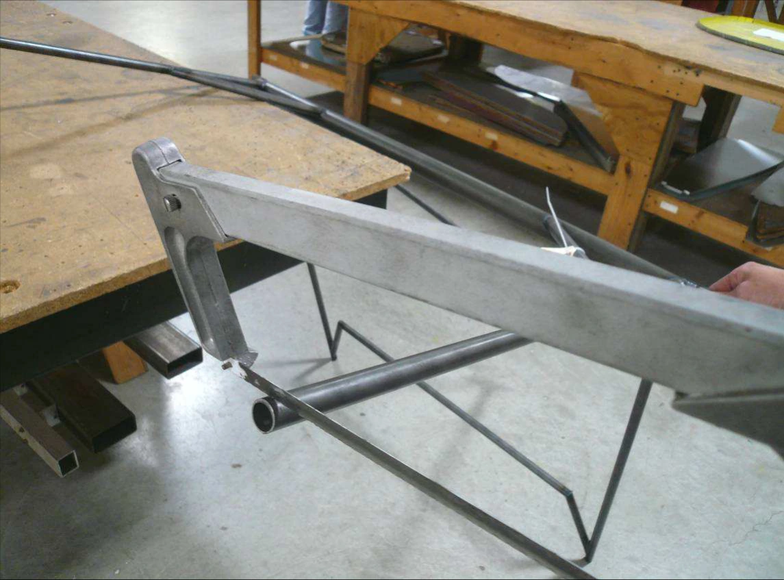
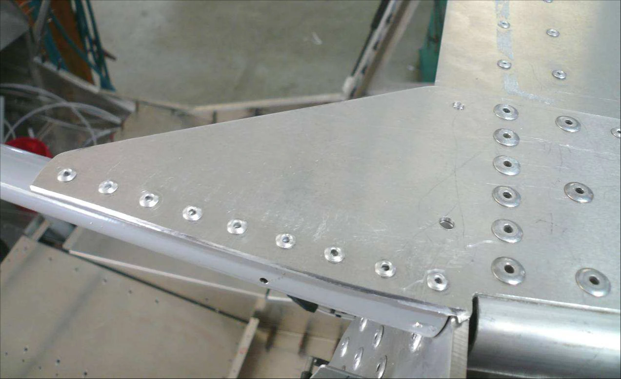
Измерьте расстояние между задним креплением крыла и первым отверстием верхнего усилителя. Перенесите его на задние верхние трубы каркаса C75F15-1.
Подрежьте припуск труб ножовкой либо подходящим отрезным инструментом. Задние верхние трубы режутся под 15°.
Так же перенесите положение отверстий борта на вертикальные трубы и подрежьте их под 5°. Точки отсчёта и ориентацию срезов сверяйте по изображению и применимому чертежу.
Сверить с исходным текстом
CRUZER
Zenith Aircraft Company
Fuselage Joining & Forward Fuselage
Section C75-FA-6 & C75-FA-7, Page 5 of 5
Revision 1.0 (12 /21/2015))
Measure the distance between the Rear Wing Attachment and the first hole in the Top Doubler.
Mark the distance measured in the previous step on the top rear tubes of the Cabin
Frame. With an Angle Grinder and Cutoff wheel or a Hacksaw, trim the excess
material off the Cabin Frame. The top rear tubes should be cut on a 15degree angle.
Follow the same procedure to mark and cut the vertical tubes for the holes in the
Cabin Side. The Vertical tubes should be cut on a 5 degree angle.
P/N: C75F15-1
Cabin Frame
CH 750 Cruzer · Соединение частей фюзеляжа · Страница 6 из 21
Крайнее заднее отверстие каркаса соедините с верхним усилителем на Cleco. Остальные сверлите #40 через усилитель в каркас, фиксируйте и увеличьте #20.
Самое нижнее отверстие борта в каркасе уже выполнено. Соедините борт с ним, затем сверлите оставшиеся #40 через борт в каркас, ставьте Cleco и увеличьте #20.
Сверить с исходным текстом
CRUZER
Zenith Aircraft Company
Fuselage Joining & Forward Fuselage
Section C75-FA-6 & C75-FA-7, Page 6 of 6
Revision 1.0 (12 /21/2015))
Cleco the aft most hole in the Cabin Frame to the Top Doubler. With a #40 drill bit, back drill through the Top
Doubler into the Cabin Frame for the remaining holes and Cleco. Then with a #20 drill bit, expand the holes
and Cleco.
The bottom most hole for the Cabin Side has been predrilled into the Cabin Frame. Cleco the Cabin Side to
the Cabin Frame. With a #40 drill bit, back drill through the Cabin Side into the Cabin Frame and Cleco.
Then with a #20 drill bit, expand the hole and Cleco.
CH 750 Cruzer · Соединение частей фюзеляжа · Страница 7 из 21
На каждой полке косынки C75F12-4 разметьте пять заклёпок и предварительно просверлите #40.
Поставьте косынку на борт и каркас, сверлите через неё #40 и ставьте Cleco. Увеличьте отверстия #20.
Соедините противопожарную перегородку с полом кабины на Cleco.
Сверить с исходным текстом
CRUZER
Zenith Aircraft Company
Fuselage Joining & Forward Fuselage
Section C75-FA-6 & C75-FA-7, Page 7 of 7
Revision 1.0 (12 /21/2015))
Layout 5 rivets on each flange of the Cabin Frame Gusset and predrill the holes
with a #40 drill bit. Position the Gusset on the Cabin Side and Cabin Frame. With a
#40 drill bit, back drill through the Gusset into the Cabin Side and the Cabin Frame
and Cleco. Then with a #20 drill bit, expand the holes and Cleco.
P/N: C75F12-4
Cabin Frame Gusset
Cleco the Firewall to the Cabin Floor.
CH 750 Cruzer · Соединение частей фюзеляжа · Страница 8 из 21
Подрежьте L-образные уголки по передним боковым листам и нанесите ось полки. Совместите её с готовыми отверстиями. Обожмите верхнюю полку по кривизне листа, сверлите #40 через лист, ставьте Cleco и увеличьте #30.
Передний уголок C75F12-7 подрежьте между перегородкой и бортом кабины. Поставьте его на L-образный уголок и измерьте посередине расстояние от его кромки до боковой обшивки.
Сверить с исходным текстом
CRUZER
Zenith Aircraft Company
Fuselage Joining & Forward Fuselage
Section C75-FA-6 & C75-FA-7, Page 8 of 8
Revision 1.0 (12 /21/2015))
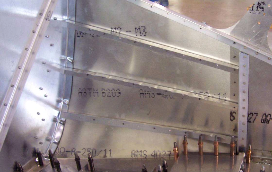
Trim L Angles to fit on the Forward Side Skin. Draw a center line on one flange of L Angles. Position the
Angles on the Forward Side Skin so the line is visible through the predrilled holes. Crimp the top flange to
match the curvature of the Side Skin. With a #40 drill bit, back drill through the Side Skin into the L Angles
and Cleco. With a #30 drill bit, expand the holes and Cleco.
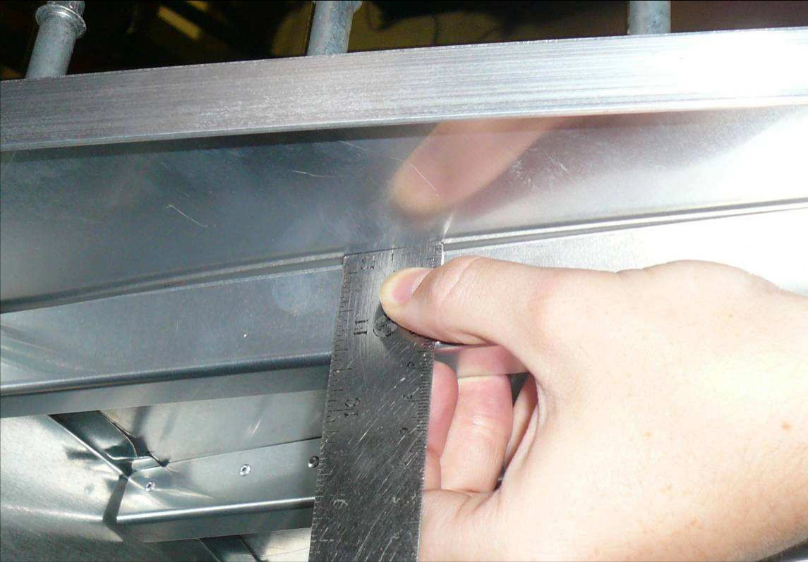
Cut the Forward Angles to fit between the Firewall and Cabin Side. Set the Forward
Angle on the L Angle and measure the distance at the center between the edge of
the Angle and the Side Skin.
P/N: C75F12-7
Forward Angle
CH 750 Cruzer · Соединение частей фюзеляжа · Страница 9 из 21
На обоих концах переднего уголка отложите измеренный ранее размер. Соедините отметки плавной кривой к середине и подрежьте по кривизне бокового листа.
Отметьте места гофров несущего уголка. Прижмите к нему передний уголок и разметьте ряд в 10mm от кромки с шагом 40mm, обходя гофры.
Угловой дрелью сверлите #40 через передний уголок в L-образный, ставьте Cleco и увеличьте отверстия #30.
Сверить с исходным текстом
CRUZER
Zenith Aircraft Company
Fuselage Joining & Forward Fuselage
Section C75-FA-6 & C75-FA-7, Page 9 of 9
Revision 1.0 (12 /21/2015))
Make a mark at each end of the Angles at the distance measured in the previous step. Make a smooth curve
to the center of the Angle from the marks at each end. Trim the Angle along the line to match the curvature
of the Side Skin.
Mark the crimp locations in the L Angle on the Side Skin. Clamp the Forward Angle to the L Angle. Layout a
40mm rivet pitch making sure to miss the crimps in the L Angle, 10mm from the edge of the Forward Angle.
With an Angle Drill and a #40 drill bit, drill the rivet locations in the Forward Angle into the L Angle and Cleco.
Use a #30 drill bit to expand the holes.
CH 750 Cruzer · Соединение частей фюзеляжа · Страница 10 из 21
Прижмите верхнюю середину перегородки к каркасу кабины. Через её полки сверлите #40 в передние боковые листы, ставьте Cleco и увеличьте #20.
Верхний узел моторамы C75F14-2 поставьте на лонжерон у перегородки. Подгоните верхний наружный угол, чтобы узел сел заподлицо с кромкой лонжерона. Перенесите край лонжерона на нижнюю поверхность узла.
Сверить с исходным текстом
CRUZER
Zenith Aircraft Company
Fuselage Joining & Forward Fuselage
Section C75-FA-6 & C75-FA-7, Page 10 of 10
Revision 1.0 (12 /21/2015))
Clamp the Firewall to the Cabin Frame at the top center of the Firewall. Use a #40 drill to back drill through
the flanges of the Firewall into the Forward Side Skins and cleco. Then expand the holes with a #20 drill and
cleco.
Position the Upper Engine Mount Fitting on the Longeron against the Firewall.
Grind the top outside corner until the Fitting will set flush with the edge of the
Longeron. Mark the edge of the Longeron on the bottom of the Fitting.
P/N: C75F14-2
Upper Engine Mount
Fitting
CH 750 Cruzer · Соединение частей фюзеляжа · Страница 11 из 21
На верхнем узле разметьте отверстие в 10mm от заднего конца по середине лонжерона и отверстие в 10mm от передней кромки лонжерона, также по его середине. Предварительно сверлите #40, поставьте узел на место, сверлите совместно, фиксируйте и увеличьте до 3/16″.
Нижний узел C75F14-1 поставьте на пол у перегородки. Его переднюю полку отцентрируйте по отверстию болта моторамы.
Проверьте расстояния до кромок у отверстий через лонжерон. Сверлите через лонжерон в узел, ставьте Cleco и увеличьте до 3/16″. Временно закрепите Cleco или болтами по показанному узлу.
Сверить с исходным текстом
CRUZER
Zenith Aircraft Company
Fuselage Joining & Forward Fuselage
Section C75-FA-6 & C75-FA-7, Page 11 of 11
Revision 1.0 (12 /21/2015))
Layout a hole 10mm from the aft end of the Upper Engine Mount Fitting centered on the Longeron. Layout a
hole 10mm from the front edge of the Longeron on the Upper Engine Mount Fitting centered on the
Longeron. With a #40 drill bit, predrill the holes for the bolts in the Upper Engine Mount Fittings. Position the
Upper Engine Mount Fitting on the Longeron, drill with a #40 drill bit, and Cleco. Expand the holes to 3/16”
and Cleco.
Position the Lower Engine Mount on the Cabin Floor against the Firewall. Center
the front flange on the hole for the Engine Mount Bolt. Check the edge distance on
the holes through the Longeron on the Lower Engine Mount Fitting. Back drill
through the Longeron into the Lower Engine Mount Fitting and Cleco. Expand the
Holes to 3/16” and Cleco or bolt.
P/N: C75F14-1
Lower Engine Mount
Fitting
CH 750 Cruzer · Соединение частей фюзеляжа · Страница 12 из 21
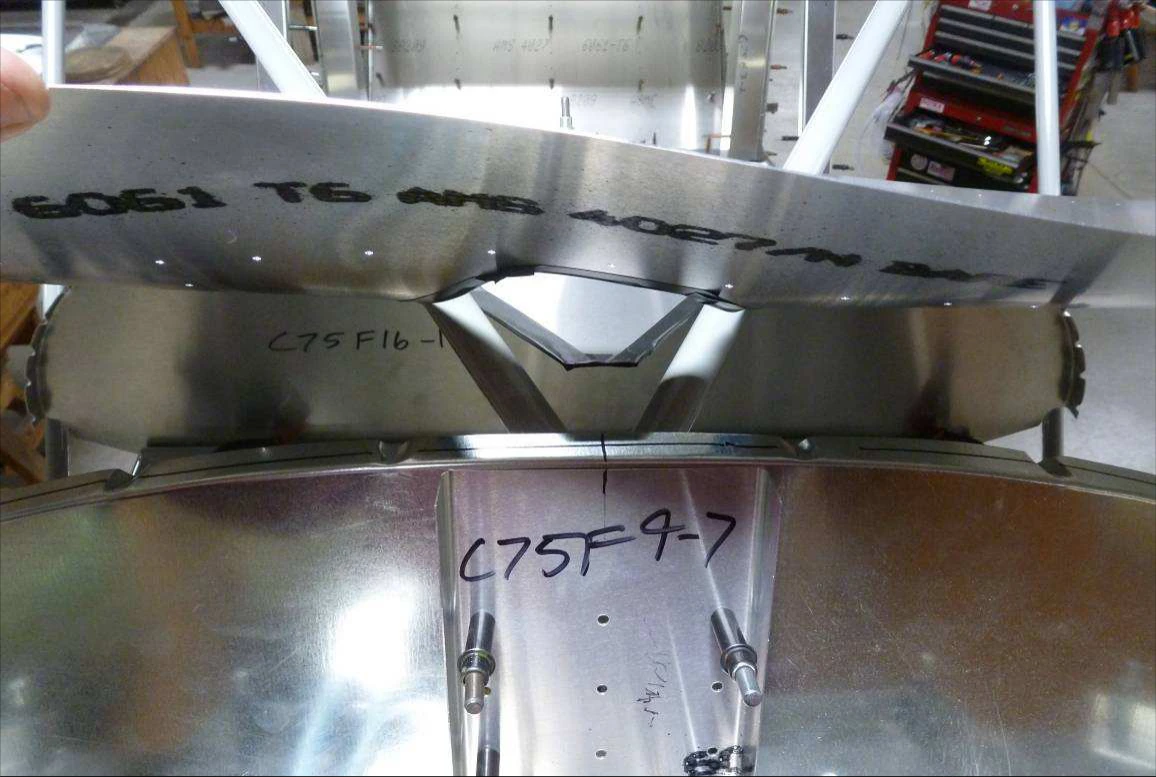
На верхней полке приборной панели C75F16-1 отметьте середину и ось полки. Выставьте панель по центру на каркасе кабины и зажмите.
Важно: сверлить панель начинают после установки переднего верхнего листа C75F16-2.
Поставьте лист над перегородкой и панелью. Центральное отверстие ряда панели совместите с пересечением её осей, сверлите #40 через лист в панель и поставьте Cleco.
Каркас проходит через вырез спереди листа. Для установки может потребоваться временно снять боковые Cleco перегородки.
Сверить с исходным текстом
CRUZER
Zenith Aircraft Company
Fuselage Joining & Forward Fuselage
Section C75-FA-6 & C75-FA-7, Page 12 of 12
Revision 1.0 (12 /21/2015))
Draw a line on the top flange of the Instrument Panel at the center and mark the
flange center line. Position the Instrument Panel on the Cabin Frame. Check to be
sure the Instrument Panel is centered. Clamp the Instrument Panel to the Cabin
Frame.
P/N: C75F16-1
Instrument Panel
Note: Wait to drill the
Instrument Panel until
the Forward Top Skin
is installed.
Position the Forward Top Skin over the Firewall and Instrument Panel. Find the
hole in the center of the Forward Top Skin for the Instrument panel and position it at
the intersection of the Instrument Panel center line and flange center line. Use a
#40 drill bit to back drill through the Skin into the Panel and cleco.
P/N: C75F16-2
Forward Top Skin
Note: The Cabin
Frame passes through
the cutout in the front
of the Forward Top
Skin and the Firewall
may need to be
unclecoed from the
sides to slip it in
position.
CH 750 Cruzer · Соединение частей фюзеляжа · Страница 13 из 21
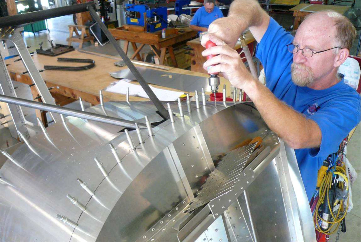
На полке перегородки нанесите осевую линию и отметьте середину сверху и спереди.
Сверлите #40 через верхний лист в перегородку от середины к краям, ставя Cleco в каждое отверстие для плотной посадки.
Через боковой лист просверлите верхний и лонжероны, поставьте Cleco. Отверстия перегородки и лонжеронов увеличьте #20, отверстия приборной панели — #30.
Сверить с исходным текстом
CRUZER
Zenith Aircraft Company
Fuselage Joining & Forward Fuselage
Section C75-FA-6 & C75-FA-7, Page 13 of 13
Revision 1.0 (12 /21/2015))
Draw a line centered on the flange of the Firewall. Also make the center of the firewall on the top flange and
front of the Firewall.
With a #40 drill bit, back drill through the Forward Top Skin into the Firewall. Start in the center and work to
each edge. Cleco every hole as they are drilled to pull the Skin tight to the Firewall. Back drill through the
Side Skin into the Top Skin and Longerons and Cleco. With a #20 drill bit, expand the holes for the Firewall
and Longeron and Cleco. With a #30 drill bit, expand the holes through the Instrument Panel.
CH 750 Cruzer · Соединение частей фюзеляжа · Страница 14 из 21
Подрежьте уголки между панелью и перегородкой, нанесите ось полки. Поставьте на верхний лист с видимой осью через его отверстия, при необходимости обожмите по кривизне, сверлите #30 и ставьте Cleco.
Узел крепления шасси C75F14-3 поставьте на фюзеляж. Задний низ заподлицо с кромкой листа, передний низ — с низом борта кабины.
Продлите заклёпочные линии на переднюю и заднюю стороны узла для разметки болтов.
Сверить с исходным текстом
CRUZER
Zenith Aircraft Company
Fuselage Joining & Forward Fuselage
Section C75-FA-6 & C75-FA-7, Page 14 of 14
Revision 1.0 (12 /21/2015))
Cut L Angles to fit between the Instrument Panel and the Firewall. Draw a center line on one flange of the L
Angles. Position the L Angles on the Top Skin so the center line is visible through the predrilled holes. Crimp
the L Angles as required to fit the skin. With a #30 drill bit, back drill through the Top Skin into the L Angles
and Cleco.
Position the Gear Strut Fitting on the Fuselage. The bottom aft should be flush with
the edge of the Skin. The bottom front should be flush with the bottom of the Cabin
Side. Extend the rivet lines onto the Gear Strut Fitting to lay out the bolt locations
on both front and rear side of the Gear Strut Fitting.
P/N: C75F14-3
Gear Strut Fitting
CH 750 Cruzer · Соединение частей фюзеляжа · Страница 15 из 21
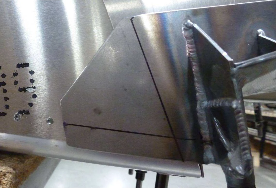
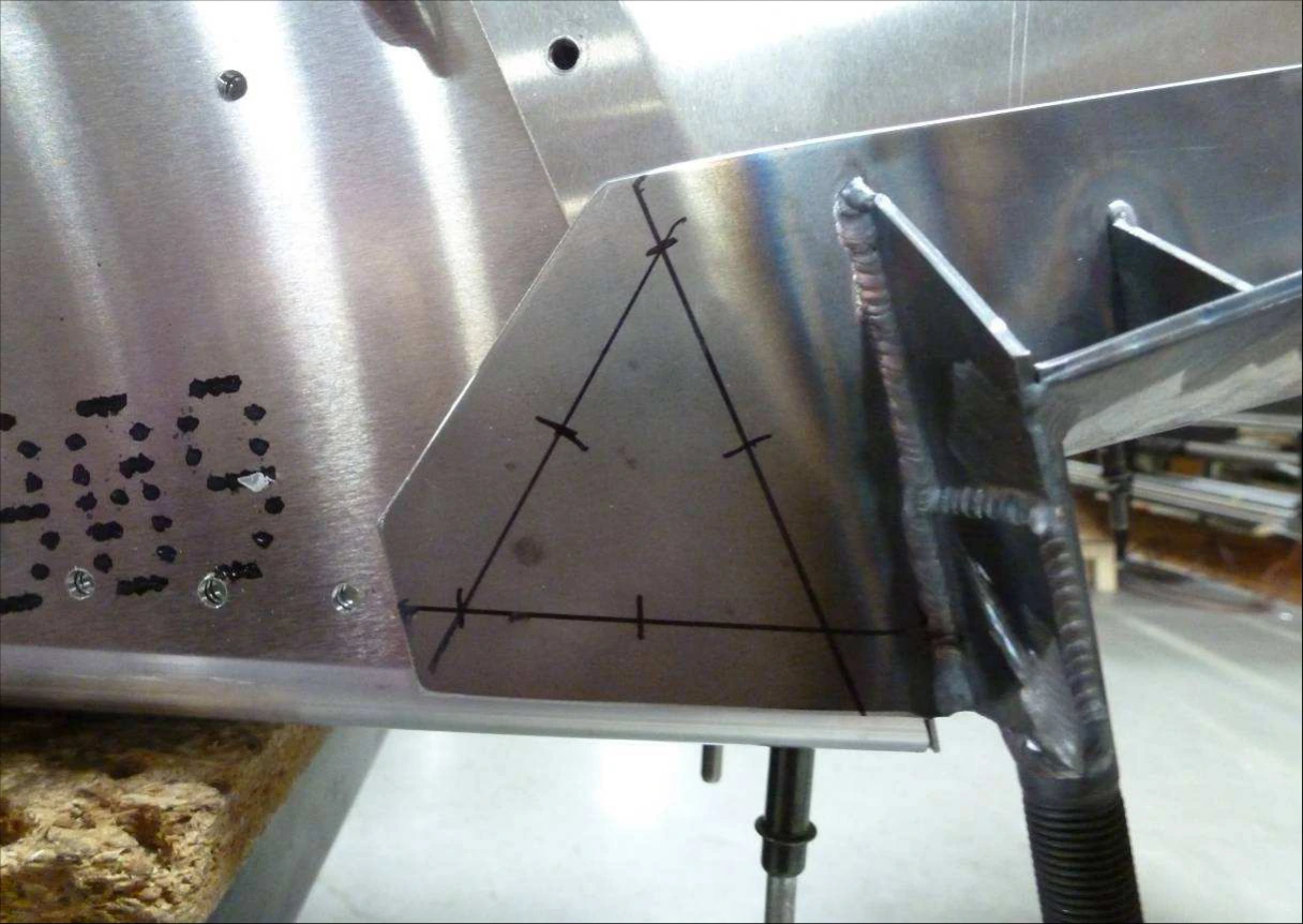
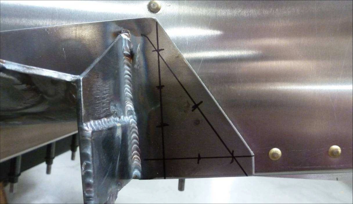
По показанному ряду разметьте отверстия в 10mm от концов и одно посередине. Между болтовыми отверстиями разметьте заклёпку в 10mm от края.
На вертикальной линии разметьте четыре равномерных болтовых отверстия. Проведите линию в 10mm от скошенной кромки и продлите нижний ряд.
Отверстие болта находится посредине между указанным пересечением и вертикальной линией; заклёпка — посередине линии вдоль скоса. Точки и стороны отсчёта сверяйте с рисунком, а не определяйте по этому описанию отдельно от него.
Сверить с исходным текстом
CRUZER
Zenith Aircraft Company
Fuselage Joining & Forward Fuselage
Section C75-FA-6 & C75-FA-7, Page 15 of 15
Revision 1.0 (12 /21/2015))
Mark a hole location 10mm from the ends and one half way between. Layout a rivet location 10mm from the
edge, half way between the bolt locations.
Extend the rivet lines and mark 4 evenly spaced bolt hole locations on the vertical line. Mark a line 10mm
from the cropped edge and extend the bottom rivet line. Mark a bolt hole location half way between the
intersection and the vertical line. Then make a rivet location centered on the line along the cropped edge.
CH 750 Cruzer · Соединение частей фюзеляжа · Страница 16 из 21
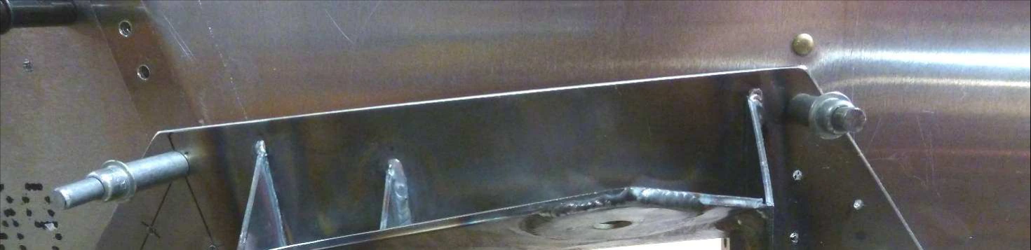
Просверлите отверстия узла шасси в фюзеляж #40, ставьте Cleco. Все увеличьте #20; десять болтовых — до 3/16″. Верхнее отверстие узла через боковой профиль увеличьте до 1/4″.
На накладке профиля шасси C75F10-2 нанесите ось. Совместите её с отверстиями узла и просверлите через них накладку.
Разметьте ещё 12 равномерных заклёпочных отверстий. Соедините накладку с профилем на Cleco, сверлите #40 через накладку, затем увеличьте #20.
Отверстия через узел крепления шасси и последнее отверстие накладки увеличьте до 3/16″ по указанному на изображении сопряжению.
Сверить с исходным текстом
CRUZER
Zenith Aircraft Company
Fuselage Joining & Forward Fuselage
Section C75-FA-6 & C75-FA-7, Page 16 of 16
Revision 1.0 (12 /21/2015))
With a #40 drill bit, drill the bolt and rivet locations on the Gear Strut Fitting into the Fuselage and cleco.
Expand all the holes with a #20 drill bit and cleco. Expand the 10 holes for the bolts to 3/16”, then expand
the top hole in the Gear Strut Fitting through the Side Channel to 1/4".
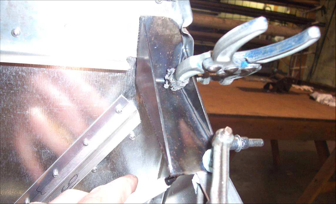
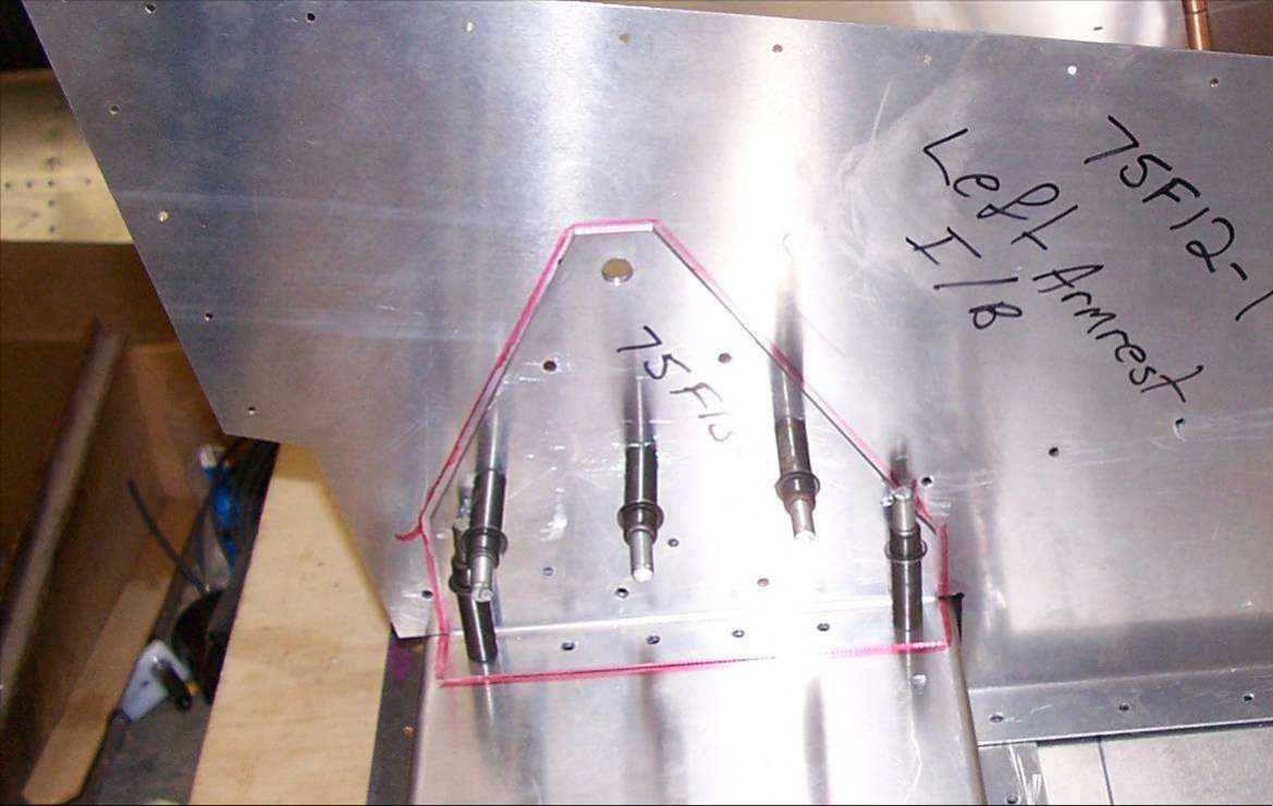
Draw a center line on the Gear Channel Doubler. Position the Gear Channel
Doubler on the Gear Channel. When the Line is visible through the holes in the
Gear Strut Fitting, back drill through the Gear Strut Fitting into the Gear Channel
Doubler (photo right). Then layout 12 rivet locations evenly spaced. Cleco the Gear
Channel Doubler to the Gear Channel. With a #40 drill bit, back drill through the
Doubler into the Gear Channel and cleco. Expand the holes with a #20 drill bit and
cleco. Expand the holes through the Gear Strut Fitting and the final hole in the
Doubler to 3/16”.
P/N: C75F10-2
Gear Channel Doubler
CH 750 Cruzer · Соединение частей фюзеляжа · Страница 17 из 21
Отрежьте уголок длиной 150mm. На оси полки разметьте крайние отверстия в 10mm от концов и ещё три равномерно между ними; начальные отверстия #40.
Поставьте уголок на профиль шасси у борта. Сверлите через уголок в борт, затем через профиль в уголок, ставьте Cleco и увеличьте #30.
Показан уголок основания сиденья C75F11-7/1 с направляющими опции сдвижного сиденья.
Сверить с исходным текстом
CRUZER
Zenith Aircraft Company
Fuselage Joining & Forward Fuselage
Section C75-FA-6 & C75-FA-7, Page 17 of 17
Revision 1.0 (12 /21/2015))
Cut a piece of L angle 150mm long. Mark the center line on one flange. Mark a rivet location 10mm from
each end of the L angle, then even space 3 more rivet locations. With a #40 drill bit, predrill the holes in the L
angle. Position the L angle on the Gear Channel against the Cabin Side. Back drill through the L angle into
the Cabin Side and cleco. Back drill through the Gear Channel into the L angle and cleco. With a #30 drill bit,
expand the holes and cleco.
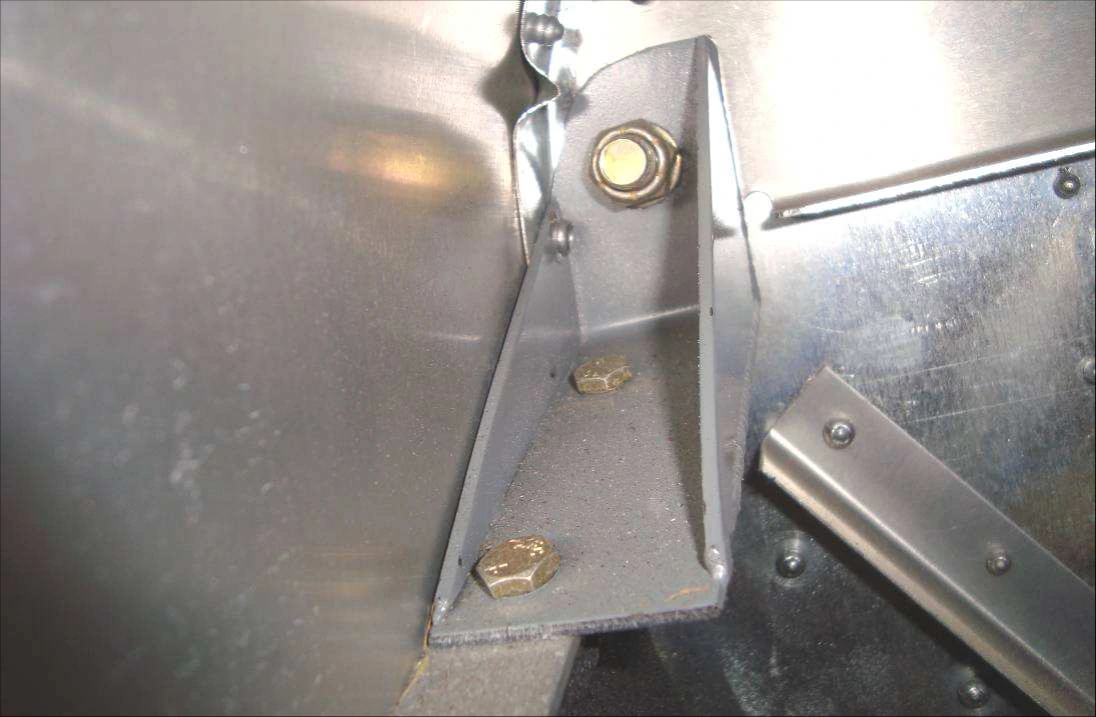
Seat base angle C75F11-7/1 (shown with the channels for the sliding seat option).
CH 750 Cruzer · Соединение частей фюзеляжа · Страница 18 из 21
Заклёпки через узел крепления шасси вытягивают с внутренней стороны.
На нижнем снимке — основание сиденья C75F11-4.
Сверить с исходным текстом
CRUZER
Zenith Aircraft Company
Fuselage Joining & Forward Fuselage
Section C75-FA-6 & C75-FA-7, Page 18 of 18
Revision 1.0 (12 /21/2015))
Rivets through the gear strut fitting are pulled from the inboard side.
Seat base C75F11-4
CH 750 Cruzer · Соединение частей фюзеляжа · Страница 19 из 21
Снимите основание, снова установите опору сиденья и боковину подлокотника. Верните основание на Cleco, оставшиеся отверстия увеличьте #30.
Сверить с исходным текстом
CRUZER
Zenith Aircraft Company
Fuselage Joining & Forward Fuselage
Section C75-FA-6 & C75-FA-7, Page 19 of 19
Revision 1.0 (12 /21/2015))
Drill the rivet line through the seat base angle C75F11-7
Remove the Seat Base and reinstall the Seat Support and Arm Rest Side. Cleco the Seat Base back in
place. With a #30 drill bit, expand the remaining holes and cleco.
CH 750 Cruzer · Соединение частей фюзеляжа · Страница 20 из 21
Поставьте внутреннее крепление ремня 75F13-7 на профиль шасси у боковины подлокотника. Сверлите #40 через крепление в боковину, затем увеличьте #20 и поставьте Cleco.
Основание сиденья находится под нижним полом багажника. Через пол сверлите в основание #40, ставьте Cleco и увеличьте #30.
Сверить с исходным текстом
CRUZER
Zenith Aircraft Company
Fuselage Joining & Forward Fuselage
Section C75-FA-6 & C75-FA-7, Page 20 of 20
Revision 1.0 (12 /21/2015))
Position the Inboard Seat Belt Attachment on the Gear Channel against the Arm Rest
Side. With a #40 drill bit, back drill through the Seat Belt Attachment into the Arm Rest
Side. Expand the holes with a #20 drill bit and Cleco.
P/N: 75F13-7
Inboard Seat Belt
Attachment
The Seat Base is positioned under the Lower Baggage Floor. With a #40 drill bit, back drill through the
Lower Baggage Floor into the Seat Base and Cleco. Expand the holes with a #30 drill bit and Cleco.
CH 750 Cruzer · Соединение частей фюзеляжа · Страница 21 из 21
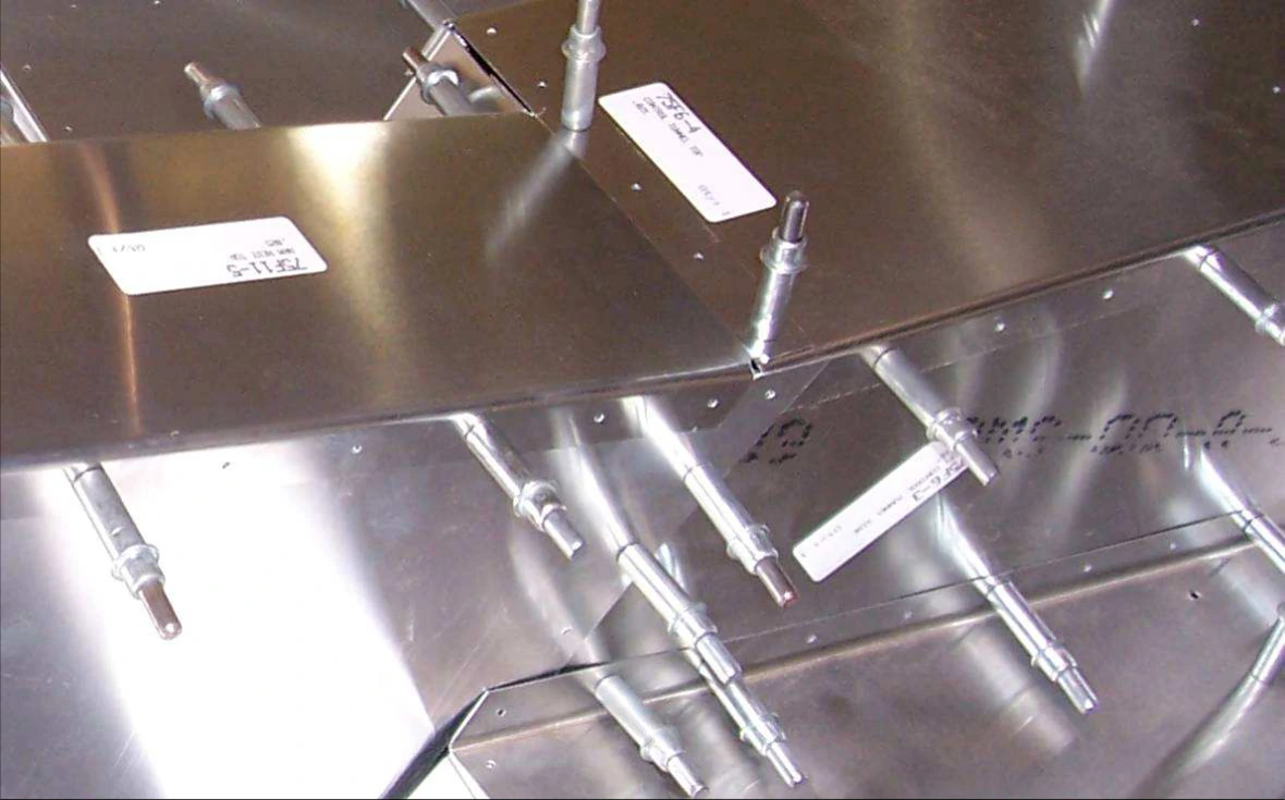
Установите верх подлокотника 75F11-5 на боковины и верх туннеля на Cleco. Отверстия этих сопряжений увеличьте #30.
Задняя полка верха подлокотника находится ПОД верхом туннеля управления.
Отверстия боковин подлокотника в боковины туннеля также увеличьте #30 и установите Cleco.
Сверить с исходным текстом
CRUZER
Zenith Aircraft Company
Fuselage Joining & Forward Fuselage
Section C75-FA-6 & C75-FA-7, Page 21 of 21
Revision 1.0 (12 /21/2015))
Cleco the Arm Rest Top to the Arm Rest Sides and to the Control Tunnel Top. With a
#30 drill bit, expand the holes through the Arm Rest Top into the Arm Rest Sides and
Control Tunnel Top.
P/N: 75F11-5
Arm Rest Top
Note: The back
flange of the Arm
Rest Top is
Clecoed under the
Control Tunnel
Top.
With a #30 drill bit, expand the holes in the Arm Rest Sides into the Control Tunnel Sides and Cleco.