c75-ta-2-elevator · 1.0 (10/01/13). Руководство CH 750 Cruzer из местного комплекта. Не подменяет применимые чертежи и их обновления. Детали и размеры версий STOL и SD в этот раздел не переносятся.
Раздел C75-TA-2 описывает руль высоты из деталей с согласованными отверстиями. Фотоинструкция дополняет чертежи и уступает им при расхождении; нормы и допуски сверяются с Construction Standards for Zenair Light Aircraft.
Сверить с исходным текстом
CH 750
CRUZER
Section C75-TA-2
Elevator
This manual has been prepared for assembly of the Elevator using match drilled parts. This photo assembly
manual is intended as a supplement to the drawings. If there is any discrepancy between this manual and
the drawings, the drawings supersede this manual. For more information on building standards and
allowable tolerances see “Construction Standards for Zenair Light Aircraft” available from Zenith Aircraft Co.
При сборке используйте чертёж C75-TA-2. Поставьте нервюры C75T3-1, C75T3-2, C75T3-3, C75T3-4, C75T3-5 и C75T3-6 в соответствующие места обшивки C75T3-10.
Передние полки соедините с листом на Cleco 1/8″.
Сверить с исходным текстом
CH 750
CRUZER
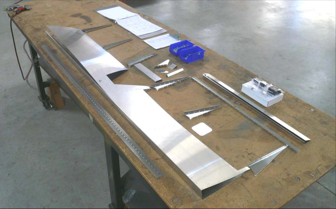
Refer to the Elevator Assembly Drawing C75-TA-2 during the construction of the
Elevator.
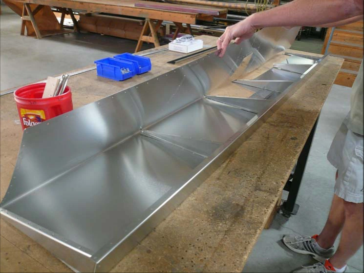
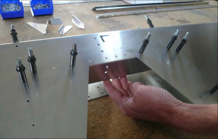
Insert the Elevator Ribs into the Elevator Skin. Position the Ribs in there correct
location.
P/N: C75T3-1,2,3,4,5,6
Elevator Ribs
P/N: C75T3-10
Elevator Skin
Cleco the front flange of the Ribs to the Skin using 1/8 clecos.
Переверните руль и соедините нижнюю сторону листа с нервюрами соответствующими Cleco.
Вставьте центральный профиль C75T3-7 и соедините его с низом обшивки фиксаторами #20.
Сверить с исходным текстом
CH 750
CRUZER
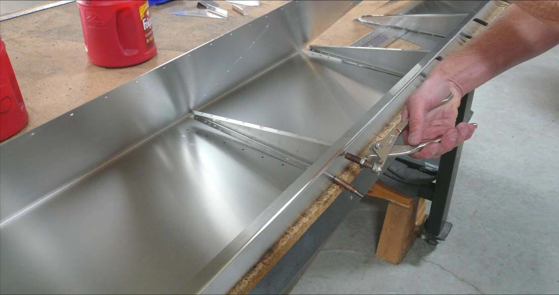
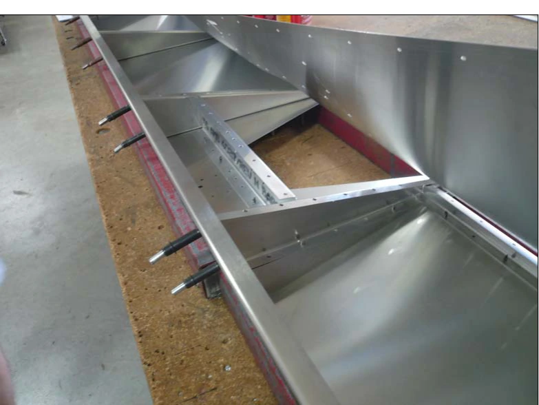
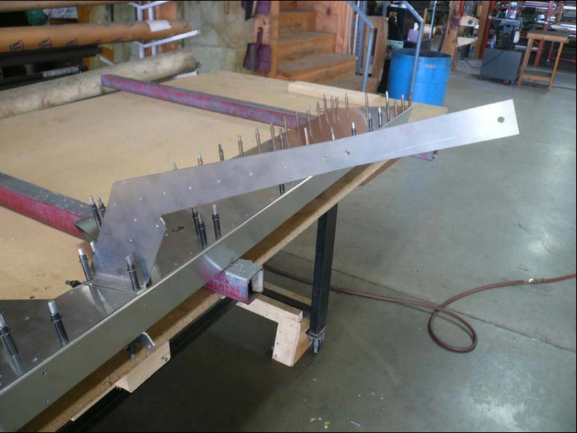
Flip the Elevator over and cleco the bottom of the Skin to the Ribs using the correct cleco.
Insert the Elevator Center Channel in the Elevator. Cleco the bottom of the Skin
and Channel together with #20 clecos.
P/N: C75T3-7
Elevator Center
Channel
Ориентация: вырез профиля находится с нижней стороны обшивки.
Сверить с исходным текстом
CH 750
CRUZER
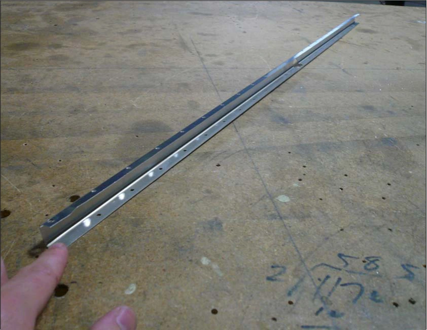
Trim Tab Channel will be position next.
P/N:C75T4-9
Trim Tab Channel
Orientation: The cutout in Channel should be installed on the bottom side of the Skin.
Заведите профиль с вырезом на место. Для доступа можно отвести наружную нервюру; нижнюю полку соедините с листом на Cleco.
Переверните руль для открытия верхнего листа и поставьте центральный профиль C75T3-7 на Cleco в середине.
Опоры высотой 2″ удерживают фиксаторы над верстаком и защищают лист от вмятин.
Сверить с исходным текстом
CH 750
CRUZER
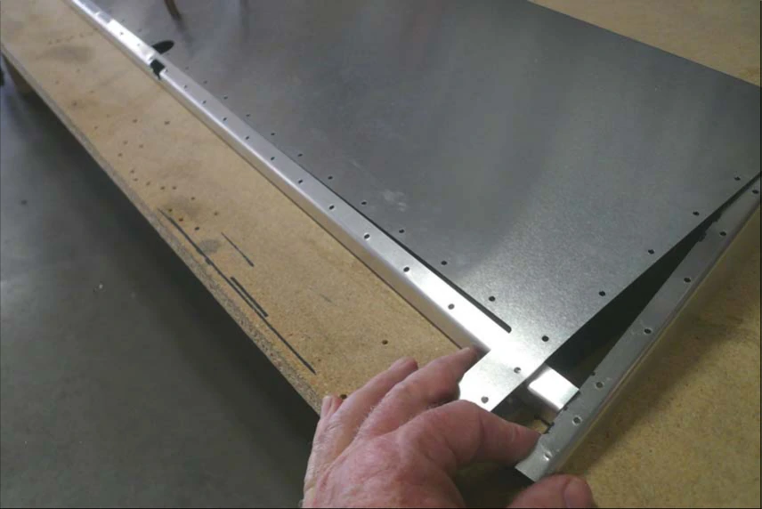
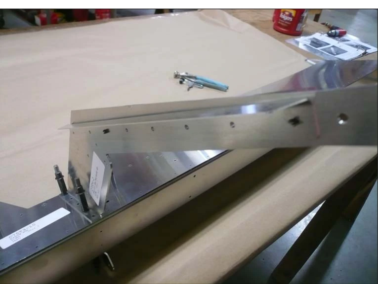
Slide the Cutout Channel into place on the Elevator. It will be helpful to pull the outboard Rib away from the
Channel to slide it in place. Cleco the bottom flange of the Channel to the Skin.
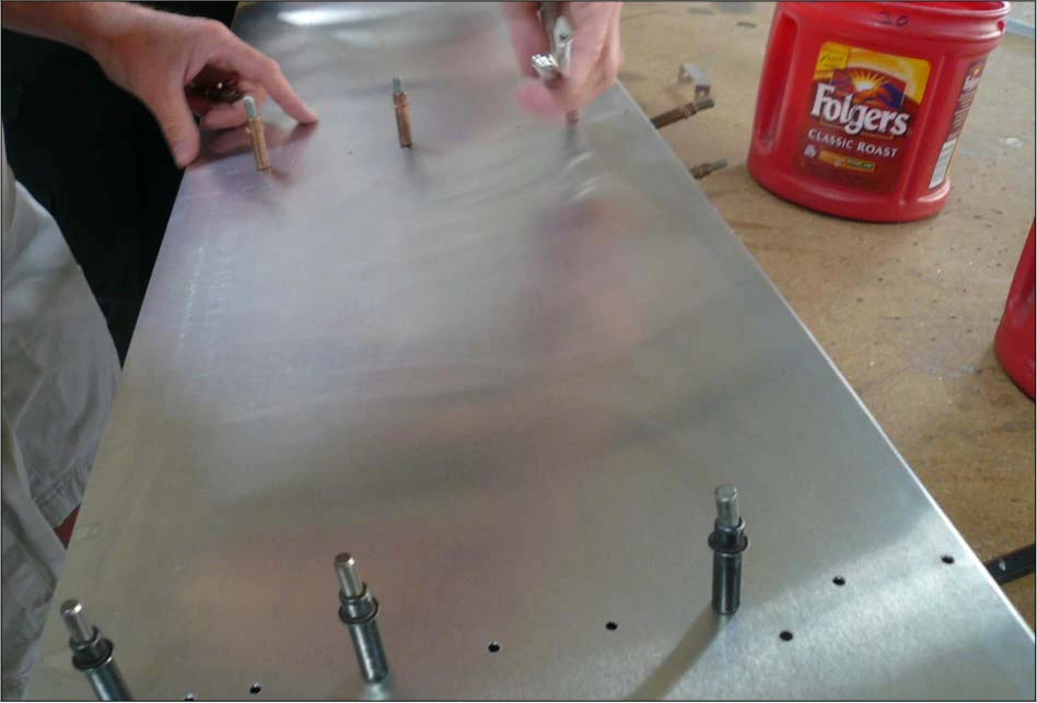
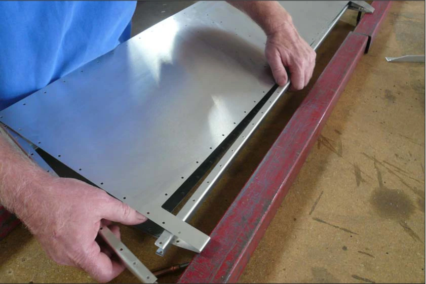
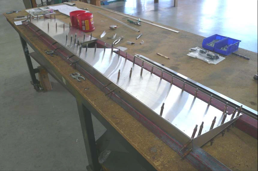
Flip the Elevator over so the top Skin can be opened. Cleco the Elevator Center
Channel the Elevator Skin in the center. Set the Elevator on 2 inch beams to
keep the clecos off the work table.
P/N: C75T3-7
Elevator Center
Channel
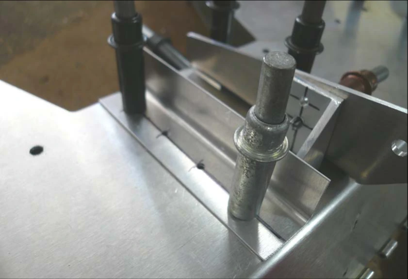
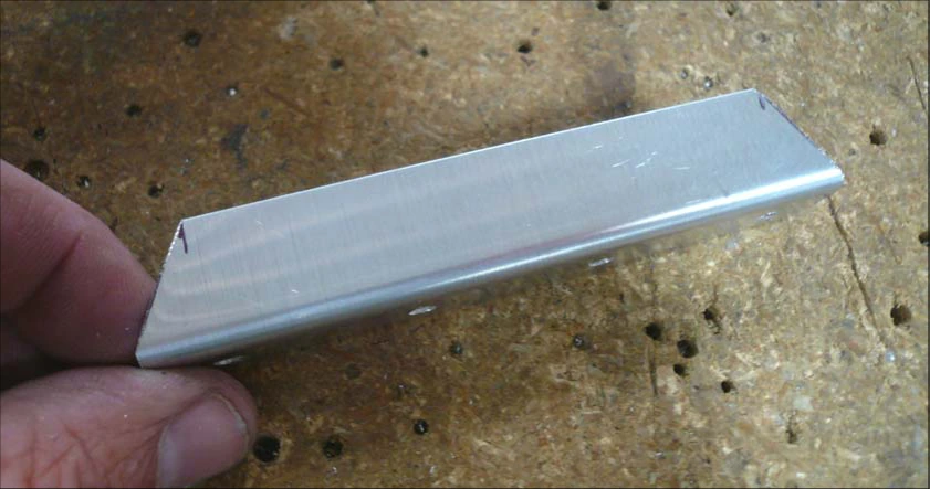
Отрежьте два уголка по 50mm. На оси одной полки разметьте отверстия в 10mm от концов и предварительно просверлите #40.
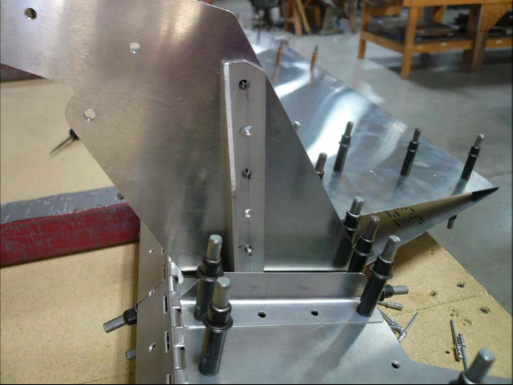
Поставьте уголок на задний профиль и внутреннюю нервюру, просверленной полкой к нервюре. Прижмите к ней, сверлите через задний профиль в уголок #30, ставьте Cleco и увеличьте #20.
Второй уголок установите и просверлите на противоположном конце профиля.
Сверить с исходным текстом
CH 750
CRUZER
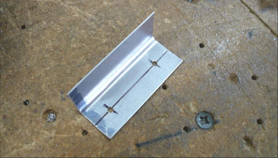
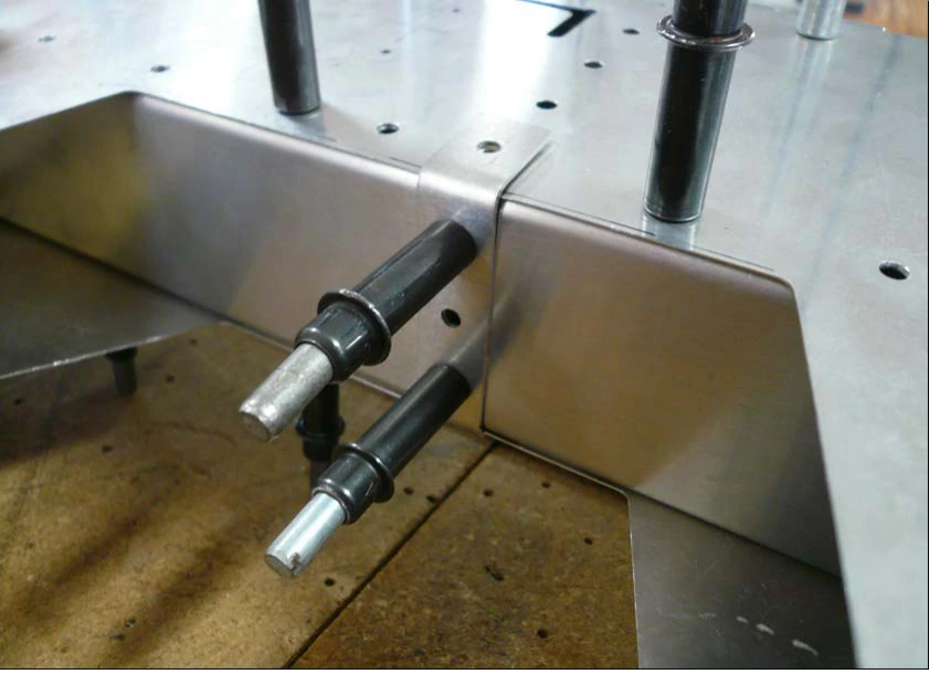
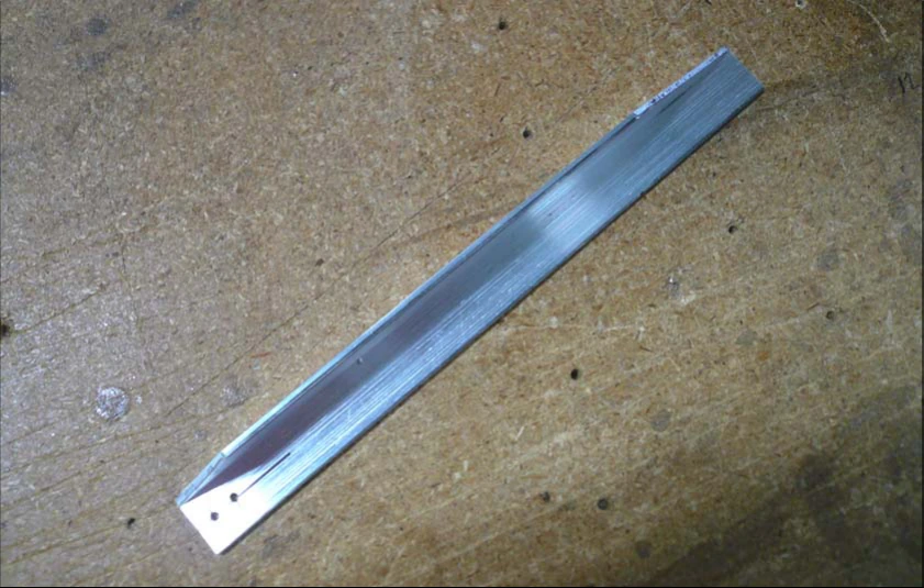
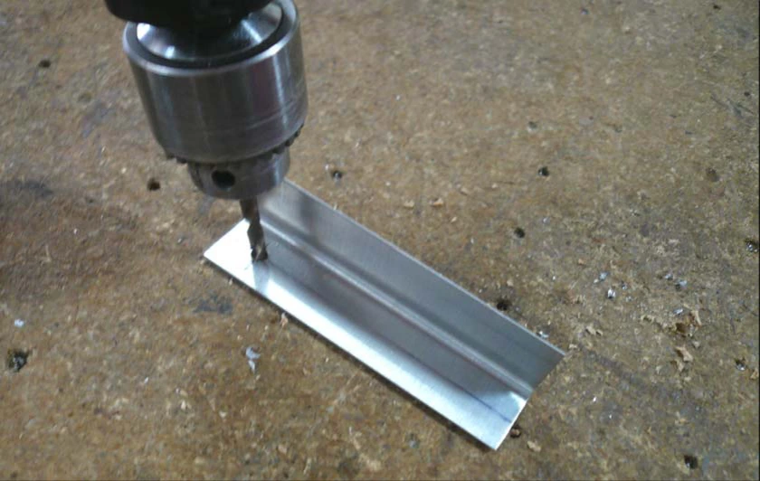
Cut two L Angles 50mm long. Draw a center line on one flange of the L Angle. Mark rivet locations 10mm
from each end of the L Angle. Use a #40 drill bit to drill the rivet locations.
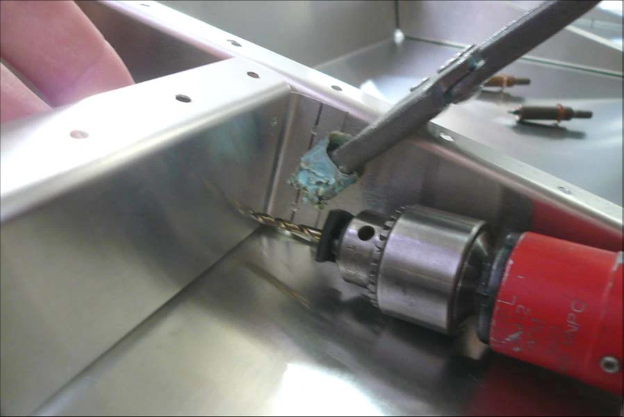
Slide the L Angle into position on the Rear Channel and Inboard Rib. Position the L Angle so the predrilled
flange is on the Inboard Rib. Clamp the L Angle to the Inboard Rib and back drill through the Rear Channel
into the L Angle with a #30 drill bit and cleco. Expand the holes with a #20 drill bit and cleco. Install and drill
the L Angle on the opposite end of the Channel.
Опустите верхний лист и закрепите его на нервюрах и профилях с Cleco; балки под узлом сохраняются.
При закрытой верхней стороне сверлите через отверстия уголков во внутренние нервюры #30, ставьте Cleco, затем увеличьте #20.
Сверить с исходным текстом
CH 750
CRUZER
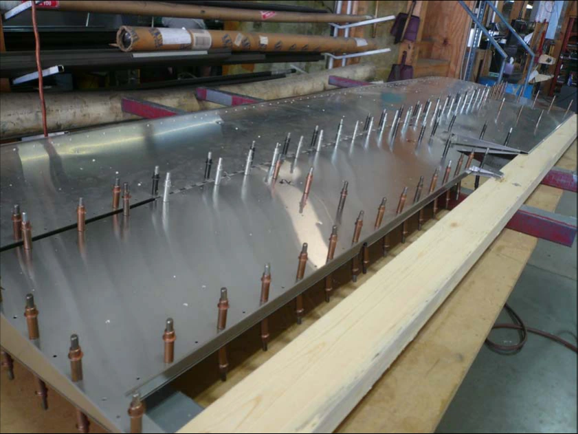
Lower the top Skin on the Elevator and cleco the Skin to the Ribs and Channels. Notice the beams keeping
the Elevator off the work bench.
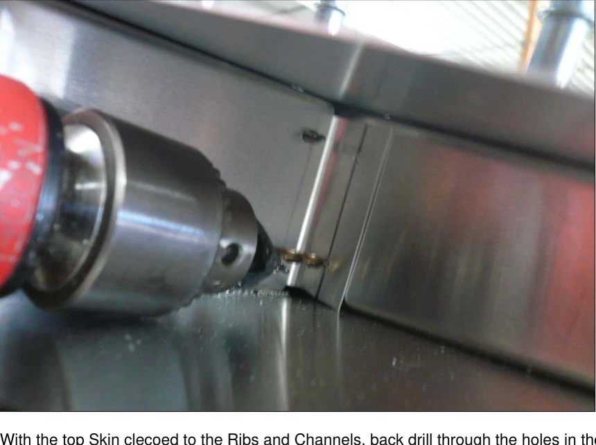
With the top Skin clecoed to the Ribs and Channels, back drill through the holes in the L Angle into the
Inboard Ribs with a #30 drill bit and cleco. Expand the holes with a #20 drill bit and cleco.
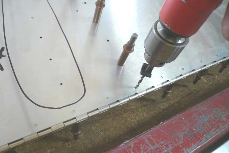
Совместите руль со стабилизатором, заведя петлю между верхним листом и полкой руля. Отцентрируйте руль на петле, установленной на стабилизаторе.
Через обшивку сверлите петлю #40, затем увеличьте все отверстия #30 и окончательно #20, устанавливая Cleco.
Сверить с исходным текстом
CH 750
CRUZER
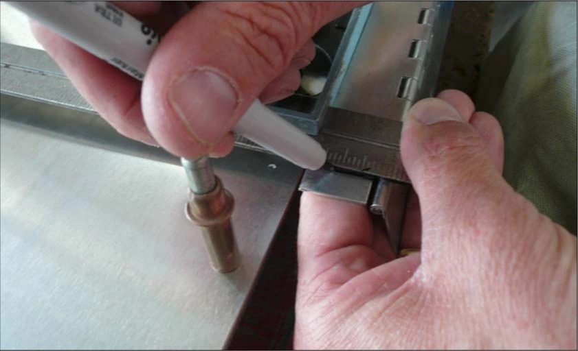
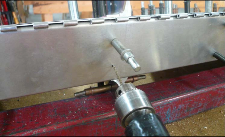
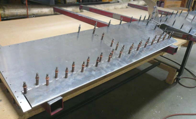
Mark a line 10mm from the end of the Piano Hinge.
P/N: C75T2-5
Piano Hinge
Position the Elevator onto the Stabilizer with the Piano Hinge. Slide the Piano Hinge between the top Skin
and flange on the Elevator. Center the Elevator onto the Hinge that is attached to the Stabilizer. Use a #40
drill to back drill through the Skin into the Hinge. Then open up all holes on the Hinge to #30 and then final
size to #20 and cleco.
Стяжку центрального профиля C75T3-11 соедините с задним профилем на Cleco #20.
Верхнюю качалку, совмещённую с рычагом массовой балансировки C75T4-2, поставьте на руль с Cleco.
Сверить с исходным текстом
CH 750
CRUZER
Cleco the Center Channel Strap to the Rear Channel with #20 Clecos.
P/N: C75T3-11
Center Channel Strap
Cleco the Upper Elevator Horn/Mass Balance Arm to the Elevator.
P/N: C75T4-2
Upper Elevator
Horn/Mass Balance
Arm
Поставьте нижнюю качалку C75T4-1 снизу руля с Cleco.
На скошенном конце усилителя C75T3-8 по размеру 20mm разметьте два отверстия: первое в 6mm от торца, второе в 8mm от первого. Начальные отверстия #40.
На обратной стороне усилителя нанесите осевую линию для позиционирования.
Сверить с исходным текстом
CH 750
CRUZER
Cleco the Lower Elevator Horn to the Elevator on the bottom side.
P/N: C75T4-1
Lower Elevator Horn
Layout two holes on the end that is cropped 20mm. The first hole is 6mm from the
end and the second hole is located 8mm from the first hole. Drill these two holes
as pilot holes with a #40 drill. On the back side of the Horn Doubler draw a center
line. This line will be used to position the Horn Doubler.
P/N: C75T3-8
Horn Doubler
По одному уголку C75T4-3 ставится с каждой стороны верхней качалки с рычагом балансировки на Cleco 1/8″.
Прижмите усилитель C75T3-8 к нижней качалке как можно ближе к её краю, сохраняя требуемые расстояния двух предварительных отверстий до кромок.
Сверить с исходным текстом
CH 750
CRUZER
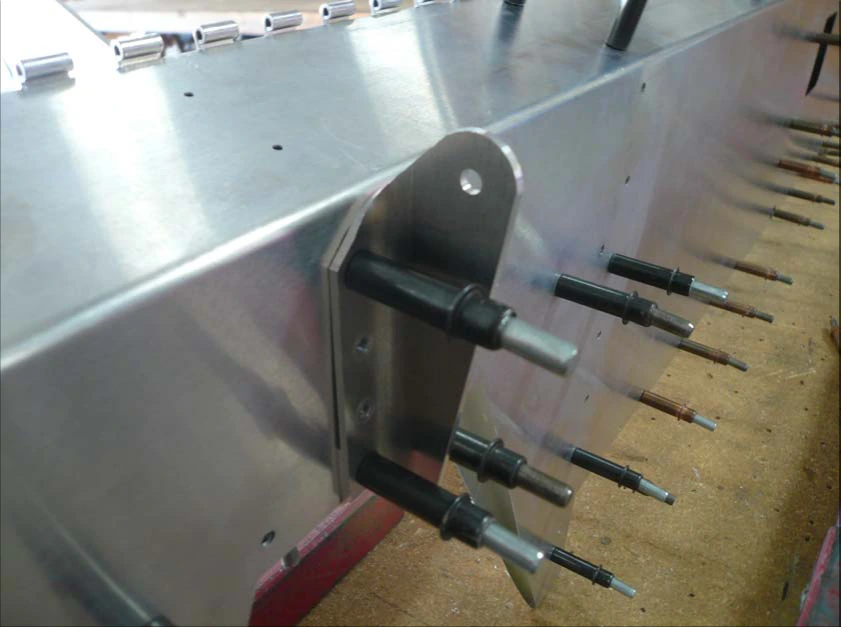
Cleco the Mass Balance Arm Angle to the Upper Elevator Horn/Mass Balance
Arm with 1/8 clecos. A Mass Balance Arm Angle is located on each side of the
Upper Elevator/Mass Balance.
P/N: C75T4-3
Mass Balance Arm
Angle
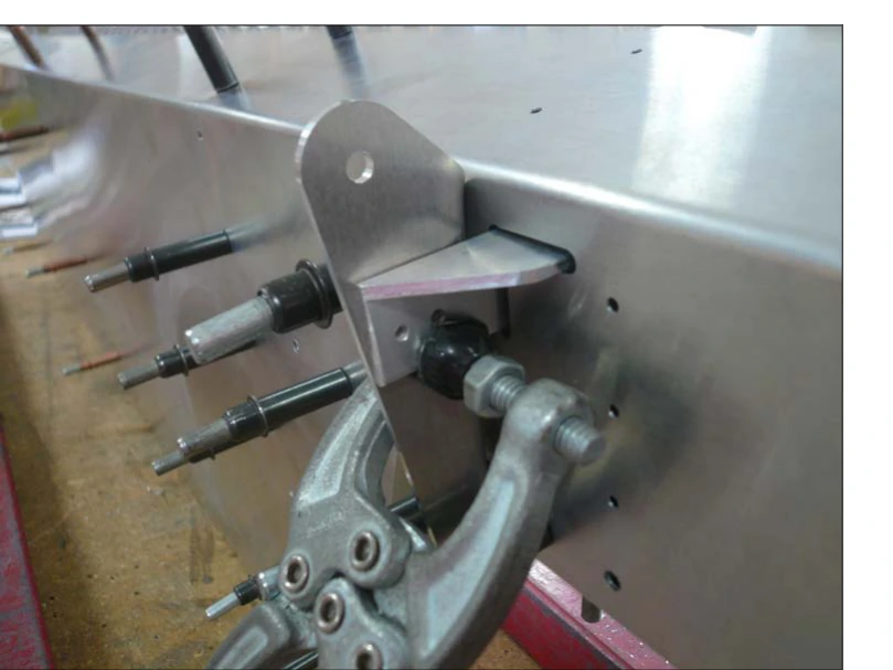
Clamp the Doubler to the Lower Horn. Position the Horn Doubler as close to the
edge of the Lower Horn as possible. Check for proper Edge Distance on the two
predrilled holes in the Horn Doubler.
P/N: C75T3-8
Horn Doubler
Вторую сторону C75T3-8 прижмите к верхней качалке/рычагу. Разметка должна быть видна через противоположные отверстия. Верхний угол при необходимости доводят напильником для зазора до уголка рычага.
Просверлите и поставьте Cleco #20. Опорный уголок C75T4-4 соедините с верхней качалкой справа на Cleco.
Сверить с исходным текстом
CH 750
CRUZER
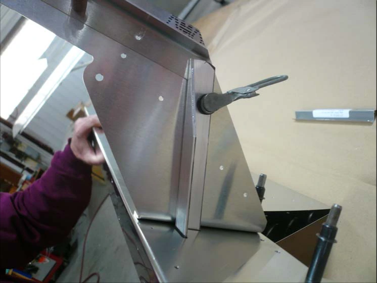
Clamp the other side of the Horn Doubler to the Upper Elevator Horn/Mass
Balance Arm. Position the Horn Doubler so the line can be seen through the holes
on the other side. The top corner may need to be filed to clear the Arm Angle.
Drill and cleco the Horn Doubler using #20 clecos.
.
P/N: C75T3-8
Horn Doubler
Cleco the Horn Support Angle to the Upper Elevator Horn/Mass Balance Arm on
the right side.
P/N: C75T4-4
Horn Support Angle
На передней полке уголка C75T3-9 нанесите ось. Снимите задний профиль, поставьте уголок к усилителю и передней стороне обшивки.
Ось должна быть видна через отверстия листа. Если не видна, маркером проверьте, хватит ли расстояния до кромки; не сверлите по догадке.
Прижмите уголок к усилителю, сверлите #40 через обшивку, ставьте Cleco и увеличьте #20.
Сверить с исходным текстом
CH 750
CRUZER
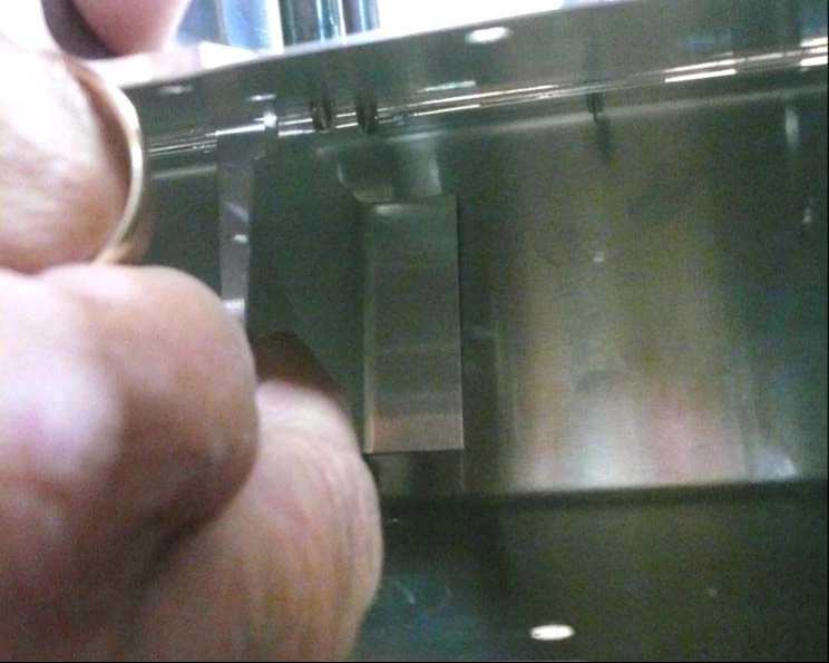
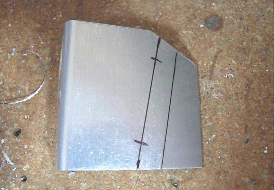
Mark a center line on the front flange of the Horn Doubler Angle.
Remove the Rear Channel from the Elevator. Position the Horn Doubler Angle
against the Doubler and the front of the Elevator Skin. The line should be visible
through the holes in the front of the Skin. If the line is not visible, use a marker
to check the holes will have sufficient edge distance. Clamp the Angle to the
Doubler.
P/N: C75T3-9
Horn Doubler Angle
Use a #40 drill bit to back drill through the holes in the Skin into the Angle and
cleco. Expand the holes to a #20 and cleco.
Перенесите задний край усилителя на уголок и снимите его. Проведите линию в 10mm от края усилителя, отметьте два отверстия в 10mm от верха и низа уголка, сверлите #40.
Верните уголок, угловой дрелью сверлите через него в усилитель #30, ставьте Cleco и увеличьте #20.
Сверить с исходным текстом
CH 750
CRUZER
Mark the aft edge of the Doubler on the Angle and remove it from the Elevator. Mark an offset line 10mm
from the edge of the Doubler. Mark two rivet locations 10mm from the top and bottom edges of the Angle.
Use a #40 drill bit to drill these rivet locations.
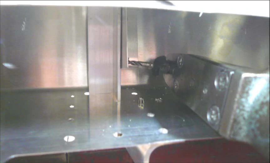
Reinstall the Angle in the Elevator. Use an Angle drill with a #30 drill bit to back drill through the Angle into
the Doubler and cleco. Expand the holes with a #20 drill bit and cleco.
Отрежьте уголки длиной 82mm и 110mm. На оси полки каждого отметьте крайние отверстия в 10mm от концов и два дополнительных равномерно между ними. Сверлите #40; самое заднее отверстие увеличьте #20.
Уголок 82mm ставится снизу. Заднее отверстие соедините с рулём и задним профилем на Cleco, сверлите остальные через уголок в руль и увеличьте #20 с фиксацией.
Сверить с исходным текстом
CH 750
CRUZER
Cut one L Angle 82mm long and another 110mm long. Mark the center line on one flange of each L Angle.
Mark the rivet locations 10mm from each end of the L angle. Evenly space 2 additional rivet locations
between the end rivet locations. Use a #40 drill bit to drill the rivet locations. Expand the aft most hole with a
#20 drill bit.
The 82mm long L Angle is installed on the bottom of the Elevator. Cleco the aft hole in the L Angle to the
Elevator and Rear Channel. Back drill through the L Angle into the Elevator and cleco. Expand the holes with
a #20 drill bit and cleco.
Уголок 110mm ставится сверху. Соедините его заднее отверстие с рулём и профилем на Cleco, просверлите остальные и увеличьте #20.
Снимите оба уголка. На непросверленной полке отметьте 10mm от конца и соедините отметку с началом радиуса сгиба. Подрежьте углы по линиям и верните на Cleco.
Сверить с исходным текстом
CH 750
CRUZER
The 110mm long L Angle is installed on the top of the Elevator. Cleco the aft hole
in the L Angle to the Elevator and Rear Channel. Back drill through the L Angle
into the Elevator and cleco. Expand the holes with a #20 drill bit and cleco.
Remove the L Angles from the Elevator. Mark a point 10mm from the end of the undrilled flange. Mark a line
from the point to the start of the bend radius. Crop the corners of the L Angles and cleco them on the
Elevator.
Петлю C75T4-10 заведите между верхним листом и профилем триммера. Край у шарнирной части заподлицо с кромкой листа. Через обшивку сверлите петлю #40, увеличьте #30 и поставьте Cleco.
Лист триммера C75T4-7 поставьте так, чтобы петля находилась между его верхом и полкой. Задняя кромка вровень с задней кромкой руля, триммер по центру выреза.
Через триммер сверлите петлю #40, затем #30 и фиксируйте Cleco.
Сверить с исходным текстом
CH 750
CRUZER
Position the Trim Tab Piano Hinge between the top Skin and the Trim Tab
Channel so the edge near the barrel of the Hinge is flush with the edge of the
Skin. Use a #40 drill bit to back drill through the Skin in to the Hinge. Use a #30
drill bit to expand the holes and cleco.
P/N: C75T4-10
Trim Tab Piano Hinge
Slide the Trim Tab Skin into position with the Hinge between the top of the Tab
Skin and the flange. Set the trailing edge of the Tab flush with the trailing edge of
the Elevator Skin. Center the Tab in the cutout. Use a #40 drill bit to back drill
through the Tab into the Hinge and cleco. Expand the holes with a #30 drill bit
and cleco.
P/N: C75T4-7
Trim Tab Skin
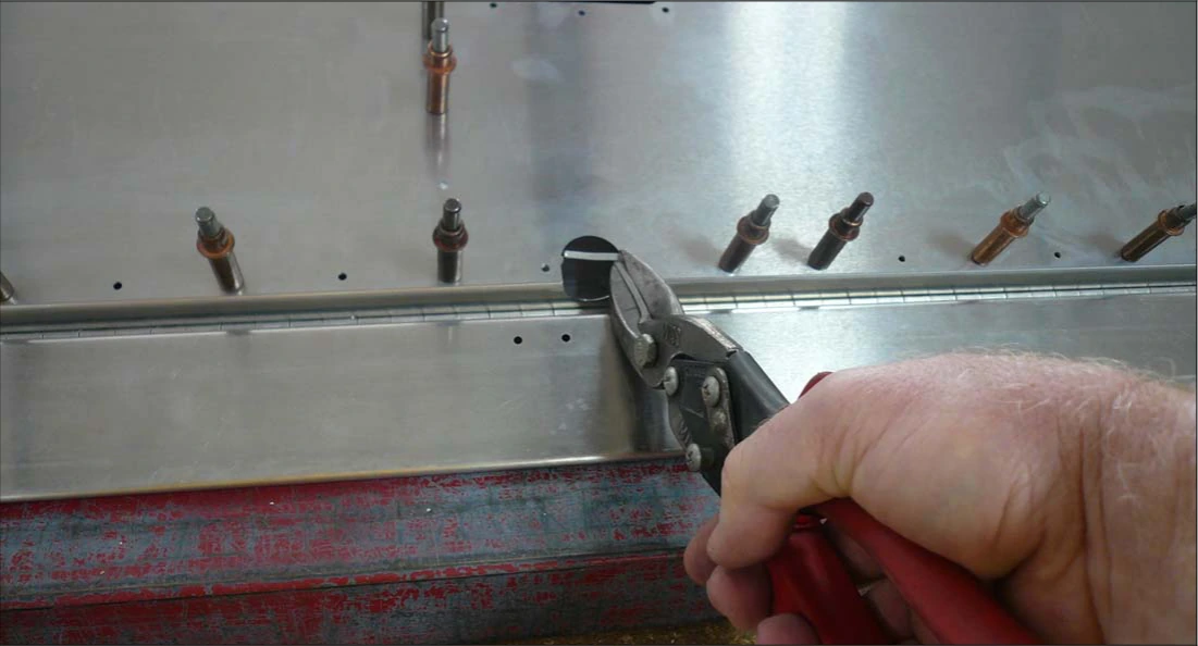
Ножницами удалите язычок снизу профиля триммера и напильником доведите срез заподлицо с обшивкой.
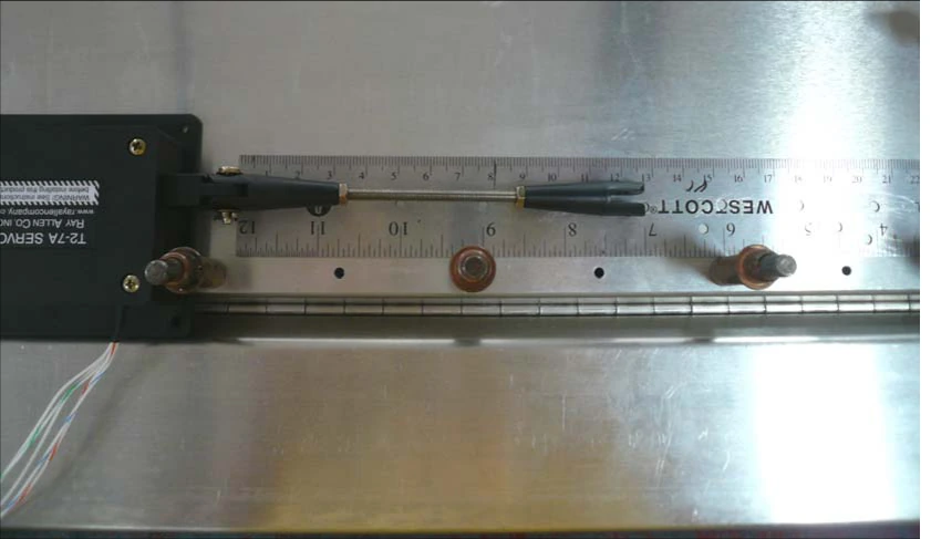
На сервопривод системы T2-7A-TS установите вилку и резьбовую тягу. Подрежьте тягу так, чтобы расстояние между вилками было 116mm, затем поставьте вторую вилку по показанному соединению.
Сверить с исходным текстом
CH 750
CRUZER
Use a pair of Snips to remove the tab on the bottom of the Trim Tab Channel. Then use a file to smooth the
cut flush to the Skin.
Install the Clevis on the Servo Motor and thread the Threaded Rod on the Clevis.
Cut the Threaded Rod so the distance between the Clevis’ is set at 116mm.
Install the Clevis on the end of the Threaded Rod.
P/N: T2-7A-TS
Trim Systems
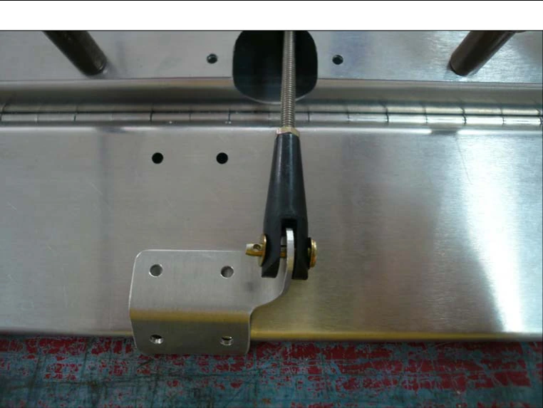
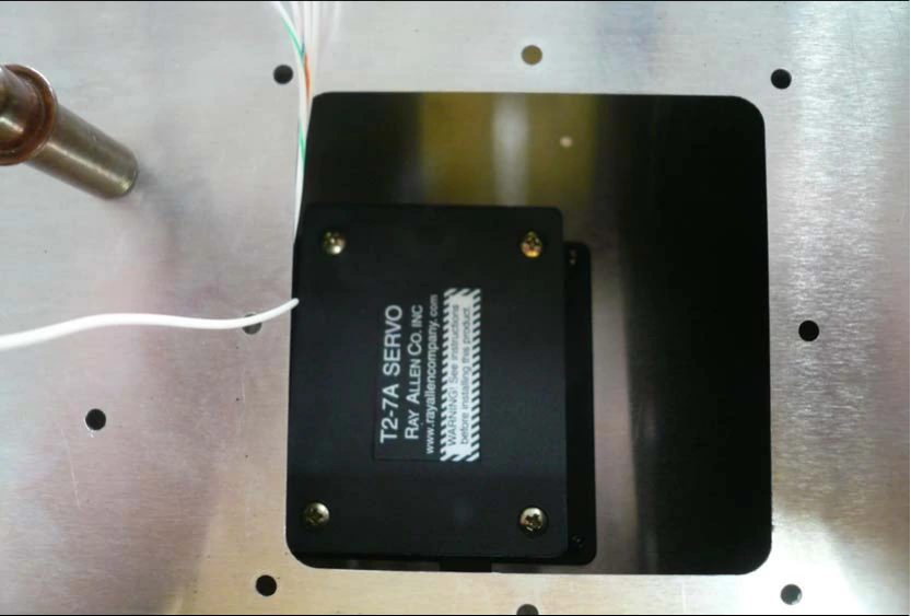
Введите привод внутрь руля, направляя тягу через вырез. Поставьте качалку C75T4-8 на вилку и соедините с триммером на Cleco.
Сам привод закрепите на верхнем листе руля с Cleco.
Сверить с исходным текстом
CH 750
CRUZER
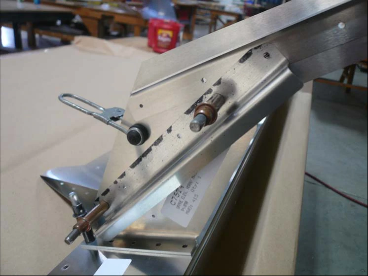
Insert the Trim Motor assembly inside the Elevator with the Rod sticking out of
the cutout. Install the Trim Tab Horn on the Clevis. Then cleco the Horn to the
Trim Tab.
P/N: C75T4-8
Trim Tab Horn
Cleco the Trim Motor to the top Skin of the Elevator.
Отрежьте уголок 268mm и заведите через отверстие доступа к приводу. Поставьте слева от него по верхней левой области чертежа C75-TA-2 и просверлите показанное сопряжение.
Четыре опоры стяжек 11-03987 расположите равномерно для удержания провода триммера. Завершите проводку и фиксацию согласно схеме привода.
Оба конца осей петель руля и триммера законтрите проволокой .032, как указано в источнике, от осевого выхода. Единицу диаметра и схему сверяйте с применимой документацией.
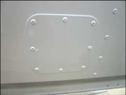
Крышка доступа может приклёпываться к обшивке по предусмотренному узлу.
Сверить с исходным текстом
CH 750
CRUZER
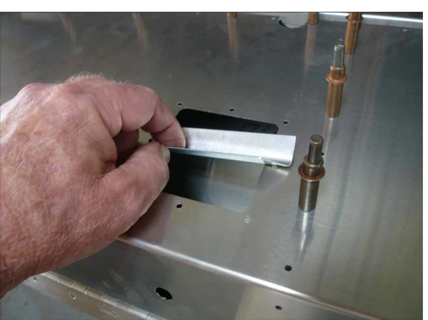
Measure and cut a “L” Angle to 268mm. Slide the Angle through the Trim Motor
Access hole. Position the Angle on the left side of the Motor. See drawing C75-
TA-2 upper left side of drawing.
Back drilling the “L’”
Angle next the Trim
Motor.
P/N: “L” Angle
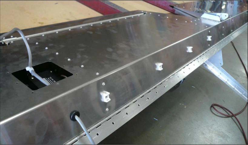
Layout 4 evenly spaced Cradle Cable Tie Mounts to secure the Trim Wire. Trim
Wire is secured using a tie wrap to the Cradle Cable Tie Mounts. Finish wiring
the Trim Motor and securing the wires. Safety Wire each end on the Paino
Hinge for the Elevator and Trim Tab using .032 Safety wire. This will keep the
rod from sliding out on each end.
Access Cover can be
riveted to the Elevator
Skin.
P/N: 11-03987
Cradle Cable Tie
Mounts
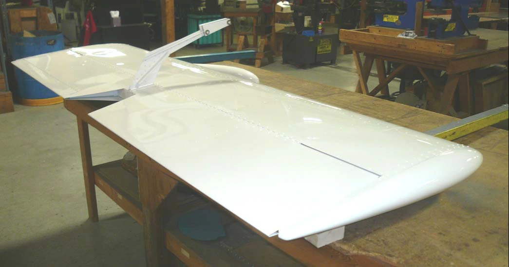
Руль и стабилизатор можно соединить и окрасить одним узлом.
После окраски и до установки на фюзеляж выполняется массовая балансировка руля по соответствующим чертежам и руководствам. Эта страница только отсылает к последующему описанию; методику и массу груза здесь не выдумывают.
Сверить с исходным текстом
CH 750
CRUZER
The Elevator and Stabilizer can be mounted together and painted as one unit. After the assembly has been
painted the Elevator can be Mass Balanced before mounting on the Fuselage. Balancing the control section
will be shown later in the Drawings and Manuals.