Редакция руководства

CH 640 Rudder Assembly Manual · Rev.0, сентябрь 2001 года. Это руководство по рулю CH 640; оно отличается от фотоальбома горизонтального оперения CH2000.

Фотографии из ссылок «увеличить» взяты в полном доступном разрешении. При расхождении размеров или отверстий приоритет имеют применимые чертежи вашего комплекта.

Порядок сборки
  1. Перед началом сборки
  2. Усилители лонжерона
  3. Нижняя задняя нервюра
  4. Остальные задние нервюры
  5. Концевая нервюра
  6. Носовая нервюра и балансир
  7. Верхняя навеска и завершение каркаса
  8. Опоры при установке обшивок
  9. Задние обшивки и сверление каркаса
  10. Носовая обшивка и подготовка к окончательной клёпке
  11. Клёпка обшивок и кабанчик
  12. Перечень деталей

CH 640 · Руль направления · Раздел 1 из 12

Перед началом сборки
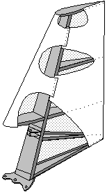
Руководство по рулю направления CH 640, редакция Rev.0 — сентябрь 2001 года. Оно дополняет подробные чертежи и руководства по самолёту. Перед началом прочитайте его целиком. В исходнике сборка хвостового комплекта оценена приблизительно в 16 часов; здесь отрабатываются основные приёмы работы с листовым металлом.

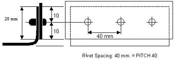
Чертежи выполнены не в масштабе. Основные размеры указаны в миллиметрах. Часть ссылок приведена только один раз, поэтому сверяйтесь с другими листами. Число крестиков на рисунке не определяет число заклёпок: используйте заданный шаг либо указанное количество. Перед работой изучите требования к инструментам и приёмы их применения.

Для этой редакции руководства приведены допуски: шаг заклёпок ±1/8″, или ±3mm; сборочные узлы ±1/8″, или ±3mm; отдельные детали ±1/16″, или ±1.5mm. Это таблица данного руководства по рулю; допуски остальных узлов берите из Design & Construction Standards и применимых чертежей.

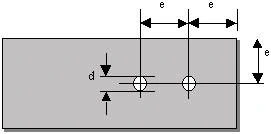
Расстояние от центра заклёпочного отверстия до края предпочтительно около трёх диаметров отверстия, обычно примерно 10mm; в исходнике минимально допустимым указано два диаметра. Соблюдайте конкретные требования чертежа.

Обращайтесь с обшивками осторожно: лист легко согнуть или заломить. Большие листы лучше переносить вдвоём, удерживая за оба конца. Берегитесь острых кромок и углов на высоте верстака; используйте защиту при работе с электроинструментом. Избегайте царапин. Поперечные риски и забоины на лонжеронах и продольных профилях зачищают вдоль детали. Обрезки пригодятся для пробных операций.

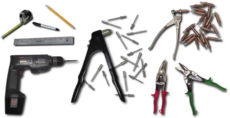
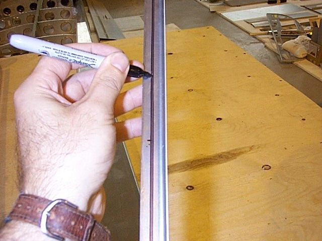
Перед сверлением размечайте взаимное положение деталей и отверстия фломастером. В этой редакции прямо сказано: НЕ использовать карандаш или ручку. Прямые линии проводите по линейке; для линии вдоль полки нервюры можно пользоваться пальцем как упором либо простым разметочным приспособлением.

Антикоррозионная обработка в исходнике описана для алюминия 6061-T6. Если она применяется, внутренние сопряжения грунтуют после снятия заусенцев и очистки, до клёпки. Для солёной или загрязнённой среды автор отдельно предлагает дополнительную защиту. Упомянуты цинк-хроматный грунт Zn-Cr, состав #656-QT и разбавитель #657-QT. Применяйте указания производителя конкретного покрытия. Окраска наружной поверхности выполняется после сборки. Исторические рекламные обещания срока службы не используются как требования к сборке.

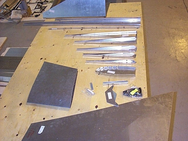
Проверьте комплектность и состояние деталей: они должны быть сухими, чистыми и неповреждёнными. Снимите ленту и этикетки. Предформованные обшивки требуют особенно осторожного обращения. Номера на деталях позволяют найти их на чертеже.

IPL — ведомости деталей и контроля сборки. В них указаны рекомендуемая последовательность, количество, описание и место для отметки об установке. После монтажа позиции отмечают в соответствующей строке.

Для руля нужны листы 640-R-1 и 640-R-2 вместе; 640-R-3; 640-R-4; 640-R-5; 640-R-6 и 640-R-7 вместе. В исходнике для этой конструкции префиксы 20- и 640- считаются обозначениями того же семейства деталей. Обозначения ниже сохранены как в руководстве; сверяйте их с редакцией чертежей своего комплекта.

Важно: детали и положение отверстий на фотографиях могут отличаться от вашего исполнения. При расхождении приоритет имеют ЧЕРТЕЖИ, а не фотографии. Техническую неясность перед изготовлением обсуждайте с поставщиком комплекта, приложив эскиз проблемы.

Сверить с исходным текстом
ZODIAC CH 640 Series Rudder Assembly Manual Click on the photo's to enlarge. Rev.0-Sept/01 HOME This rudder assembly manual has been organized to help the first-time builder assemble the rudder tail kit. The rudder kit requires an estimated 16 hours to assemble, and provides the builder with an excellent introduction to building the complete kit, covering most of the skills and techniques needed to assemble the rest of the aircraft kit (the rudder is basically a diminutive version of the wing). INTRODUCTION Building your own aircraft is probably going to be one of the most challenging and rewarding things you will do in your lifetime: imagine, you'll be flying in an aircraft that you have built yourself! Few people get the sensation and freedom of flying. Even fewer also get the reward of flying a plane that they've built themselves! The most difficult part of the project will be getting started: Don't become overwhelmed. While it's true that an aircraft is a piece of complex machinery, it is also very simple, especially when building from a kit. It's normal that you may initially become overwhelmed and confused, but your initial fears and concerns will disappear as soon as the project starts coming together, and as you get a better understanding of the construction. The ZODIAC CH 640 is a well-designed light aircraft — using proven materials and simple processes and systems. This RUDDER ASSEMBLY MANUAL has been prepared as a supplement to the complete and detailed Drawings and Manuals for the ZODIAC CH 640 series aircraft. READ THE ENTIRE RUDDER ASSEMBLY MANUAL BEFORE STARTING. GETTING STARTED READING THE ASSEMBLY INSTRUCTIONS: The detailed Assembly Instructions have been prepared so that the complete airframe may be built from the parts supplied in the kit. The drawings are not to scale, and provided measurements are metric (millimetres). All the required references are provided in the Assembly Instructions, but often only once (this may require some cross-referencing). For rivet holes, do not count the "X"s shown on the drawing: Either the pitch (distance between holes) is specified, or the number of holes (rivets) is specified. Updates to the Assembly Instructions are published in the Zenair Newsletter (back-issues are available). Read first: — Required Tools — Using Your Tools — Before Starting WORKING TOLERANCES: When assembling the Rudder , the pre-formed parts fit together properly, but certain tolerances must be observed. Always follow the specified dimensions as closely as possible, but remember to be practical and use common sense (you're building a well-designed light aircraft, not a jet fighter). Follow these tolerances: Click on the photo's to enlarge. TYPE INCHES METRIC Rivet Spacing +/- 1/8" +/- 3 mm. Assemblies +/- 1/8" +/- 3 mm. Parts +/- 1/16" +/- 1.5 mm. See the Design & Constructions Standards Manual for detailed tolerances for the rest or the aircraft. Edge Distance (e) = 3 X Rivet Diameter (d) EDGE DISTANCE : When positioning rivets, you must provide proper "Edge Distance" (the distance from the rivet or rivet hole to the edge of the material) for structural strength: The edge distance should be about three times the rivet hole diameter, usually approx. 10 mm. (with two times the diameter the minimum acceptable edge distance): Working with sheet metal : Handle sheet metal parts with care. Sheet metal skins can easily be damaged (bent or kinked) when handled. With larger skins, it is recommended that two people handle them (one on each end). Be careful with sharp corners and sheet-metal edges. Be especially careful with children around sheet-metal corners at eye level (workbench height). Always wear proper protection when working with power tools and around sharp sheet-metal parts. Think Safety First!! Avoid scratching the material, but do not worry about light surface scratches. On spars and longerons, transverse scratches and nicks must be removed by filing and sanding lengthwise to remove scratches. Don't throw away cut-offs — you may find a use for such parts at a later date, or you can use them as "practice" pieces. DRAWING AND MARKING : Before drilling or positioning parts together, draw the position on the part(s) and hole marks. Use a felt-tip marker to draw. Do not use a pencil or pen. Use a straight edge to mark straight lines. To draw lines along a rib flange, it's often easier to simply use your hand (finger) as a reference, or you can use a simple "marking" tool. CORROSION PROTECTION : The aircraft has been designed to minimize exposure to corrosion problems. In the usual environment, no additional corrosion protection is required. However, you may want to add corrosion protection, especially if you will operate or store the aircraft near salt water and/or in a polluted industrial area. To add corrosion protection, the internal structure must be primed with Zinc-Chromate (Zn-Cr) primer. This must be applied before parts are riveted together. In the kit, pre-riveted parts, such as the wing spars, have been primed at the factory. NOTICE: If using Zinc-Chromate primer, follow the primer manufacturer's directions. Purchase yourself some Zinc Chromate Primer from Aircraft spruce 877-4-SPRUCE. Zinc Chromate Primer #656-QT with reducer #657-QT. Once you are ready to rivet the parts together, after deburring and cleaning, brush-on (paint) the inside only. The aircraft aluminum used is 6061-T6 which is already very corrosive resistant. Adding Zinc Chromate Primer will make it last 50+ years. Paint primer is added to the outside of the aircraft, once the aircraft is finished. That will protect it from corrosion. All old aircraft use 2024-T4 aluminum which is more than 30% more corrosive than 6061-T6. Questions or problems as you're building? Think your question or problem through. Often the answer and solution is very obvious and logical. If you can't solve it yourself, feel free to contact AMD with your questions . Remember, it's best that you submit technical questions on paper: draw us a sketch of your problem, and FAX or mail it to us for a prompt response, or call or email us. You will need all the kit parts that make up the rudder tail section: You will notice that the parts are conveniently labelled for easy identification. The first three numbers indicate the page number on which the part appears in the Drawings and the last number is the specific part number as it appears on the Drawing: Each assembly of the aircraft is broken up into sections such as the Left Wing, Right Wing, Rudder etc.. Each section is detailed in the Inspection Parts Lists (IPL). The IPL’s are used when assembling the aircraft. The IPL lists the parts in the recommended assembly sequence, with parts quantity, description and a sign off area. so that once you have installed a part, you initial the one line. The IPL’s are unique to the CH 640 and were originally designed for the FAA certified CH2000. Click on the photo's to enlarge. Drawings: Only five pages of the actual Drawings are needed to assemble the rudder: 640-R-1 and 640-R-2 together, 640-R-3, 640-R-4, 640-R-5, 640-R-6 and 640-R-7 together. Note: the first drawing numbers 20- or 640- are assumed to be for the same aircraft. Drawings List: Inspect all the parts that make up the rudder section. Notice that you can verify all part dimensions and specifications against those shown in the Drawings (the drawings are actual blueprints and not just assembly drawings). Make sure the parts are in good shape, dry and clean (remove tape, labels, etc.). HANDLE THE PARTS WITH CARE , ESPECIALLY PRE-FORMED SKINS. Please note that parts and hole locations in the following photos may not be the exactly the same as the parts you have or the drawings. When questioning, the drawings are always correct. NOT the photos.

CH 640 · Руль направления · Раздел 2 из 12

Усилители лонжерона
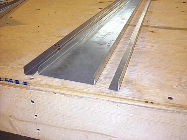
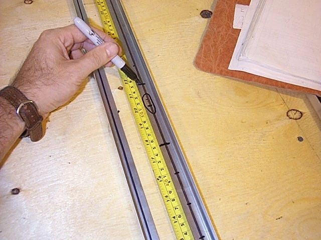
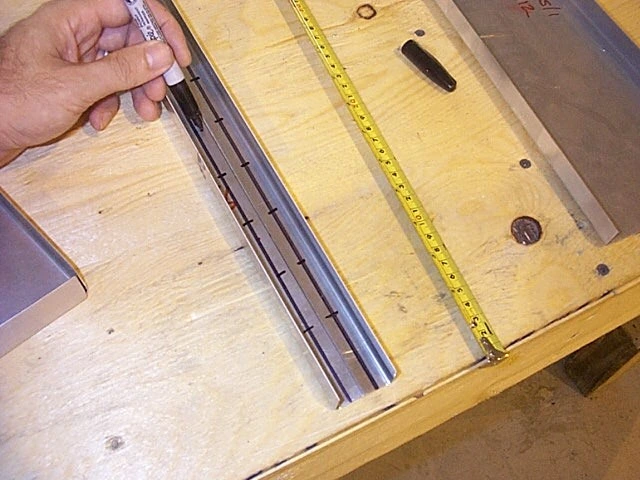
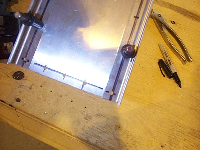
Разместите уголки-усилители 20-R-2-6 внутри лонжерона 20-R-2-5 по чертежу 640-R-2. Проведите осевые линии по внутренним сторонам полок усилителей.

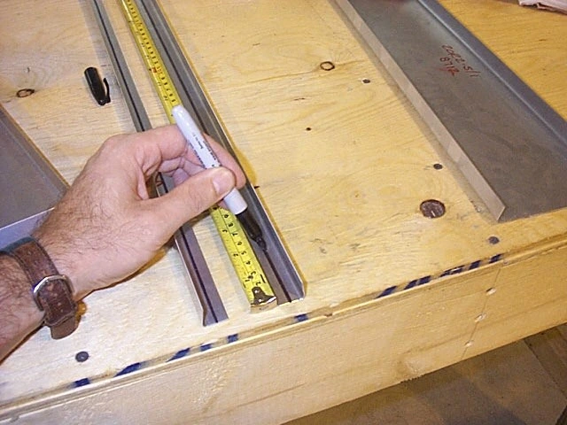
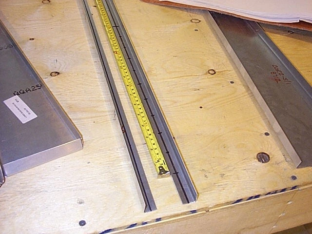
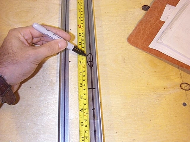
Разметку отверстий начинайте СНИЗУ. Первое отверстие расположено в 50mm от нижнего края лонжерона. Далее на участке длиной 400mm отверстия идут через 40mm; следующее — через 30mm, затем через 35mm, затем через 50mm, затем три отверстия через 40mm и далее по чертежу. Обозначение p.40 означает шаг 40mm или меньше.

До сверления отметьте положение носовой нервюры и всех других нервюр по 640-R-5: отверстия не должны попадать в запрещённые участки. Особенно отметьте верхние кронштейны навески 20-R-4-2: их положение задано на высоте 510mm от низа, между кронштейнами зазор 10mm. Этот участок лонжерона пока не сверлите.

При сверлении через готовое отверстие не увеличивайте его без необходимости. Если трудно удержать размер, первое отверстие можно выполнить меньшим сверлом, а затем рассверлить до указанного. Не нажимайте так сильно, чтобы сверло прогибало нижнюю деталь.

Размечая ряд, сначала определите крайние отверстия с нужными отступами, затем равномерно распределите промежуточные по заданному шагу. В исходнике допускается небольшая корректировка шага на один-два миллиметра; при этом нельзя терять требуемые отступы или заменять размерный чертёж счётом нарисованных крестиков.

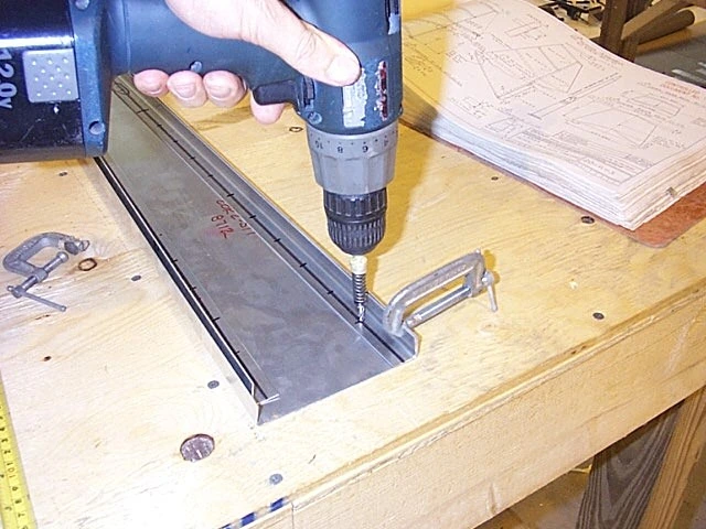
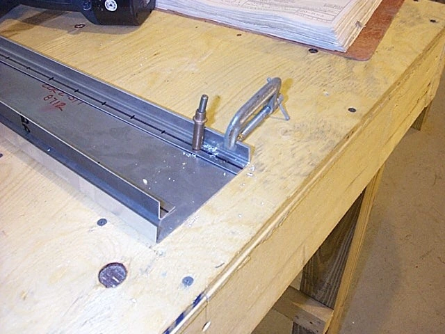
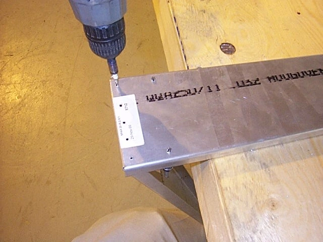
После разметки первого усилителя положите усилители рядом и перенесите линии на второй. Прижмите их по месту. Просверлите лонжерон сверлом #30 через разметку первого усилителя, затем второго. Устанавливайте Cleco по мере сверления, в том числе через одно отверстие, удерживая сборку плоско на верстаке.

Cleco должны надёжно фиксировать детали; ставить их в каждое отверстие обычно не требуется. Если при сверлении нужно чрезмерное усилие, проверьте остроту сверла и при необходимости заточите или замените его.

Сверить с исходным текстом
Positioning the Doubler Angles (20-R-2-6) inside the SPAR (20-R-2-5) The Doublers are reinforcements for the SPAR section, positioned inside the SPAR as shown on Drawing 640-R-2 . To start, mark center lines along the inside of the SPAR doublers (in the middle of the Doubler flange). Mark hole positions as per drawing 640-R-2, STARTING AT THE BOTTOM . Note: first hole starts 50 mm from the bottom of the spar. After that, there is one hole very 40 mm over a length of 400 mm. The next hole is 30 mm up, than 35 mm up, than 50 mm up, than three holes 40 mm apart etc.. (p. 40 means that there should be a hole every 40 mm or less). Make sure that the nose rib location at the spar is marked and that there will be no holes in that areas. NOTE THE LOCATION OF THE UPPER HINGE BRACKETS 20-R-4-2 ON DRAWING 640-R-5. The hinge brackets are located 510 from the bottom. There is a 10mm gap between them. Mark the area down on the spar and do not drill in that area. Mark all the rib locations as per 640-R-5 before drilling the spar doublers. Mark these areas clearly. Know where everything will be before drilling the spar holes. HINT ON DRILLING : When drilling through an existing hole, avoid enlarging that hole. If you find this to be a problem, consider under-sizing your first hole, and then re-drilling it to proper size later. Also, don't press too hard with the drill (this will minimize drill ‘travel’) and prevent the part underneath from bending under the drill's pressure. HINT ON MARKING HOLES : When measuring the pitch (hole distance) along a straight line, start by marking the first and last holes (with the proper edge distance at both ends). Then proceed to mark the additional holes (in between the two end marks) at the required pitch. Always try to keep the pitch consistent (unless otherwise instructed): This may require adding or subtracting a millimetre or two to the pitch. As a rule of thumb, it's better to add an extra rivet than to spare one when making these slight adjustments to the pitch. Remember, the "x"s on the Drawings do not always accurately illustrate the number of rivets: Read the requested Pitch (or specified number of rivets), and remember the required Edge Distance. Remember to provide proper edge distance. Once you have marked each hole location, put the doublers beside each other and transfer the marker line to the other doubler, saving time measuring again. Clamp the doublers in place. Once positioned properly, drill the marked hole locations into the SPAR (#30 drill). Repeat with other doubler. After drilling every other hole, place a cleco in the hole to clamp the assembly together. Drill all marked doubler holes. Cleco the parts as you drill. Use the cleco's as clamps to hold the assembly down flat on the bench. HINT : Never worry about using too many clecos. The more clecos you use, the better your parts are being held together. However, you'll rarely need a cleco in every hole. HINT : Keep drill bits SHARP. The drill bit is probably dull if you find you have to press too hard with your drill: sharpen or replace the bit. Click on the photo's to enlarge.

CH 640 · Руль направления · Раздел 3 из 12

Нижняя задняя нервюра
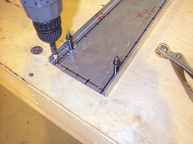
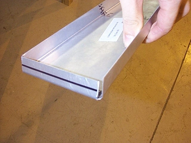
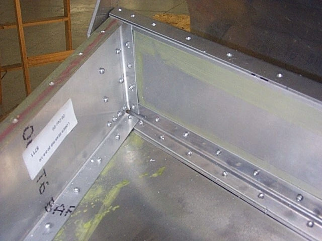
Установите заднюю нижнюю нервюру 20-R-6-1 по чертежу 640-R-5. На лонжероне проведите прямую линию в 10mm от нижнего края и наметьте на ней пять равномерно расположенных отверстий с соблюдением отступов. Просверлите пять отверстий сверлом #30. Дополнительно смотрите узел Lower Rear Rib на листе 640-R-7.

На полке нервюры 20-R-6-1 проведите осевую линию фломастером. Вставьте нервюру в лонжерон; совместите её разметку с центрами отверстий лонжерона. Прижмите нервюру и просверлите её через готовые отверстия, устанавливая Cleco по ходу работы.

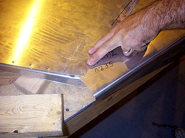
Таким же способом устанавливают остальные нервюры: размечают и сверлят лонжерон, проводят линию на полке нервюры, совмещают её через отверстия, прижимают и сверлят. На одной фотографии 20-R-6-1 уже показана вместе с обшивкой; обшивку на этом этапе НЕ устанавливают.

Сверить с исходным текстом
Installing Rear Rib (20-R-6-1) to the Spar (SPAR) As shown on Drawing 640-R-5. 20-R-6-1 — Draw a straight line 10mm parallel to the bottom spar edge. Mark five (5) evenly spaced drill holes along the line (remember Edge Distance). Holes in the flange (#30 drill). Also See 640-R-7 drawing detail "Lower Rear Rib" Drill the five holes. Mark a center line on rib 20-R-6-1 flange with marker as shown. Take the rib and position it inside the spar as shown. Through the drilled holes, locate the rib marker flange line so that the marker line is centered in the holes. The rib is now positioned. No measuring required! Clamp the rib to the spar and drill into the rib through the existing drilled spar holes. The other ribs are located using the same method. ie Mark the rib and hole locations on the spar and drill the rivet holes Mark a straight line on the rib flange Install the rib by lining up the rib marker line through the spar holes Clap rib to spar and drill through the pre-drilled spar holes Cleco as you drill This photo shows the final installation of 20-R-6-1 with the skin, not to be installed at this time.

CH 640 · Руль направления · Раздел 4 из 12

Остальные задние нервюры
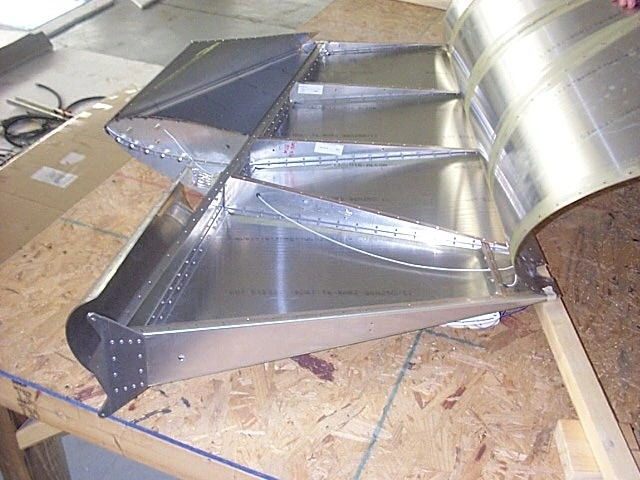
Нервюры 20-R-6-2, 20-R-6-3 и 20-R-6-4 устанавливаются тем же способом, что и 20-R-6-1; расположение смотрите на 640-R-5.

Для 20-R-6-2 отложите 550mm от нижнего края собранного лонжерона и проведите поперечную линию, перпендикулярную его оси. Это ось полки нервюры. Наметьте три заклёпочных отверстия в пределах полки и просверлите лонжерон. Смотрите также нервюры №2, №3 и №4 на листе 640-R-4.

20-R-6-3 располагается в 720mm от низа лонжерона; 20-R-6-4 — в 1080mm. Точные привязки указаны на 640-R-5.

Если нервюра упирается в усилители внутри лонжерона, её можно слегка подрезать ручными ножницами, равномерно с обеих сторон. Не удаляйте лишний материал сверх необходимой подгонки.

Сверить с исходным текстом
Positioning 20-R-6-2 and 20-R-6-3 and 20-R-6-4 to the SPAR . See Drawing 640-R-5 Install the other ribs by using exactly the same procedure as 20-R-6-1. 20-R-6-2 : As shown on Drawing 640-R-5, measure up 550 from the bottom of the spar assembly, and mark a straight line (perpendicular to center of SPAR) across the SPAR where 20-R-6-2 will be positioned. That location is the center line of the rib flange. Mark 3 rivet holes making sure that they will be in the rib flange, and drill the 3 holes in the spar. See 640-R-4 drawing, rib #2,3 and 4. 20-R-6-3 is located 720mm from the bottom of the spar. 20-R-6-4 i s located 1080mm from the bottom of the spar. Drawing 640-R-5 will give you the exact dimensions. NOTICE : The Ribs may require a little trimming to clear the spar doublers inside the SPAR assembly. If required, trim lightly with hand snips, evenly on both sides. Don't trim too much.

CH 640 · Руль направления · Раздел 5 из 12

Концевая нервюра
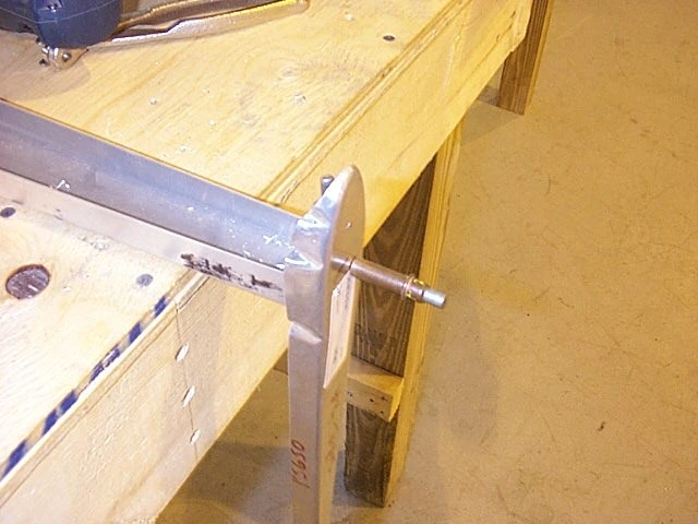
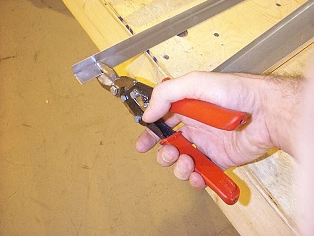
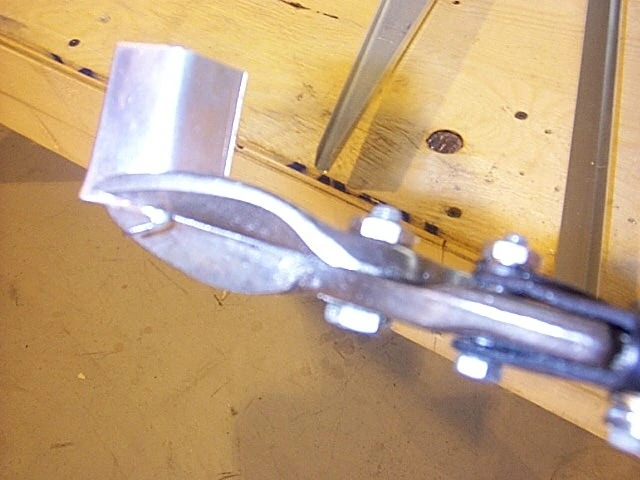
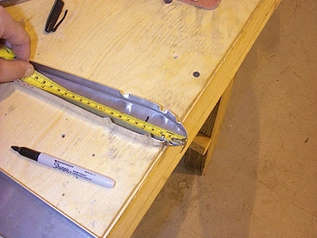
Для концевой нервюры 20-R-3-2 отрежьте от стандартного L-образного уголка с углом 90° и исходной длиной 4 фута участок 35mm. Смотрите узел Tip Rib на 640-R-4. Сначала делайте черновой рез, затем чистовой: так требуется меньше зачистки напильником.

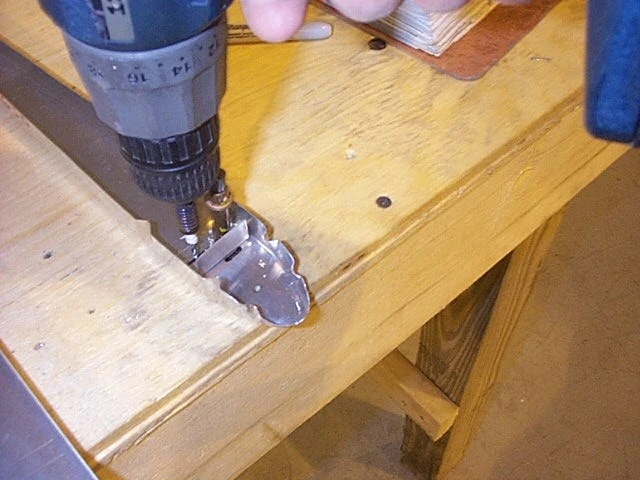
На нервюре отметьте положение уголка по чертежу: в 50mm от законцовки. Приложите уголок и просверлите два отверстия. Важно: размер 50mm на узле Tip Rib листа 640-R-4 задан от конца нервюры до лонжерона; проверьте правильность расположения уголка.

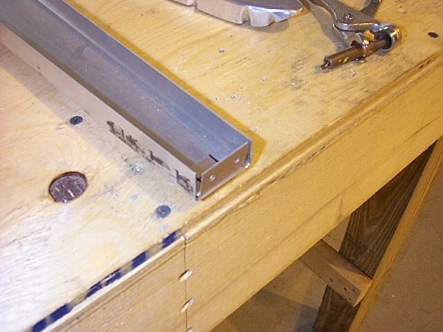
Выставьте уголок у верхнего конца лонжерона, прижмите, просверлите и закрепите Cleco. Соедините узел целиком.

Сверить с исходным текстом
Positioning the Tip Rib 20-R-3-2 Take an L Angle (90 degree shaped angle, 4 feet long) and cut off 35mm. See drawing 640-R-4 Tip Rib. Note: When cutting with the snips, always do a rough cut first. Then do a final cut which will be much cleaner. This will save a lot of filing time. Take the tip rib 20-R-3-2 and mark the location of the L angles as per drawing 640-R-4 Tip Rib. It is located 50mm from the tip. Mark a line as shown. Position the L angle to the rib and drill two holes. Note that the 50mm on drawing 640-R-4 Tip Rib is from the tip of the rib to the spar. Make sure that the L angles is properly located. Now locate the same L angle to the spar tip as shown on drawing 640-R-4 Tip Rib. Clamp, drill and cleco the L angle in place. Put the assembly together.

CH 640 · Руль направления · Раздел 6 из 12

Носовая нервюра и балансир

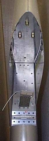
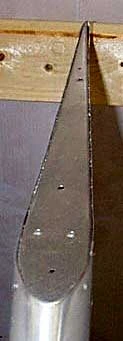
Носовая нервюра 20-R-3-1 расположена в 740mm от низа лонжерона. Её полка у лонжерона направлена вверх.

Разметьте положение нервюры и пять отверстий: по одному в каждом усилителе лонжерона и три между ними. Просверлите отверстия. На полке нервюры проведите ось, совместите её через отверстия, прижмите и просверлите, устанавливая Cleco.

В передней части 20-R-3-1 находится балансир 20-R-5-5. Выставьте его, прижмите и просверлите крепления. Он не должен выступать за переднюю кромку нервюры и мешать будущей носовой обшивке. Снимите балансир после примерки.

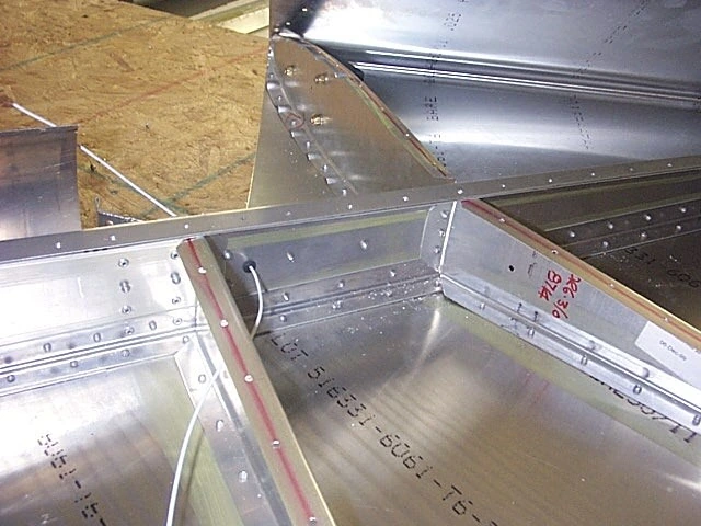
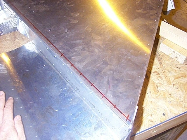
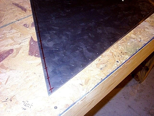
Проведите осевые линии на полках всех нервюр и на лонжероне: они понадобятся при установке обшивок. На фотографиях эти линии отмечены красным.

Сверить с исходным текстом
Positioning the Nose Rib 20-R-3-1 The Nose Rib is positioned 740mm from the bottom of the spar. Note that the flange is up at the spar. Mark the rib and hole locations on the spar and drill the rivet holes. five in total. One in each spar doubler and three in the middle. Mark a straight line on the rib flange Install the rib by lining up the rib marker line through the spar holes Clap rib to spar and drill through the pre-drilled spar holes Cleco as you drill There is a Balance Mass (20-R-5-5) located on the front of 20-R-3-1. Locate, clamp and drill. Make sure that it does not extend past the front of the rib so as not to interfere with the nose skin, to be installed later. Remove the Balance Mass. Draw center lines across all the rib flanges and spar. These lines will be used l when positioning the skins over the ribs. See red marker lines in photo.

CH 640 · Руль направления · Раздел 7 из 12

Верхняя навеска и завершение каркаса
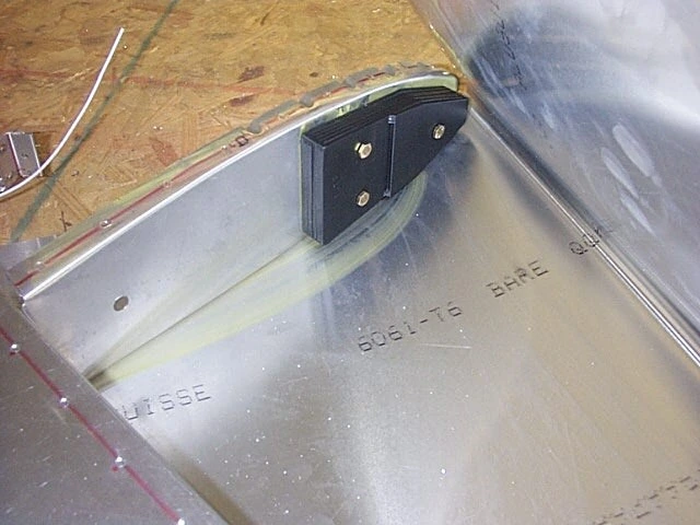
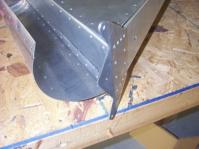
Теперь установите верхние кронштейны навески 20-R-4-2 по 640-R-5. Верхняя поверхность нижнего кронштейна находится в 510mm от низа лонжерона. Верхний кронштейн расположен на 10mm выше нижнего; смотрите 640-R-5 и 640-R-4. Прижмите и просверлите оба кронштейна.

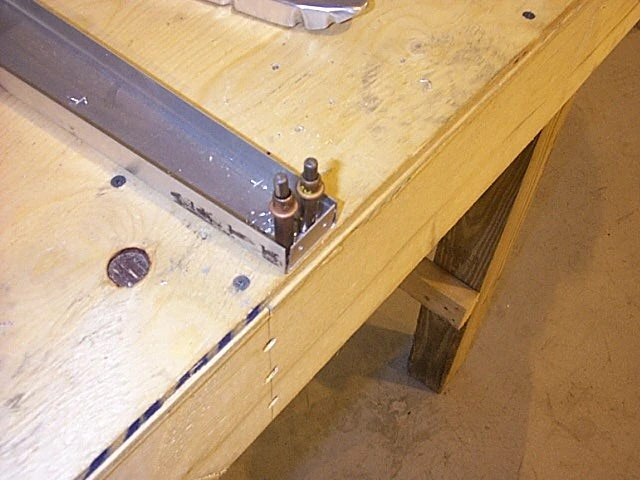
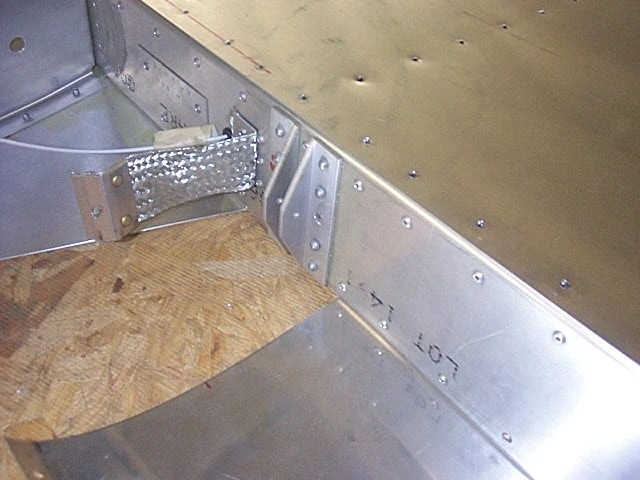
Снимите кронштейны, обработайте их напильником до гладкого контура, без грубых кромок. Приклепайте на место, заводя заклёпки с внутренней стороны. Толстая перемычка, показанная рядом с кронштейнами на фотографиях, относится к молниезащите и устанавливается позднее.

Каркас руля собран. Перед разборкой полезно провести несколько совмещённых меток через соседние детали, чтобы затем восстановить их взаимное положение. Снимите Cleco, разберите узел и удалите заусенцы из отверстий и с кромок. При необходимости после зачистки нанесите антикоррозионное покрытие. В труднодоступных местах используйте плоский напильник.

Снова соберите каркас на Cleco и склепайте. Головку заклёпки располагайте со стороны более тонкого материала. Если заклёпка не проходит из-за небольшого несовпадения отверстий, в исходнике предлагается осторожно пройти их сверлом; не увеличивайте размер произвольно.

Сверить с исходным текстом
The Upper Hinge Brackets (20-R-4-2) can now be installed as shown on drawing 640-R-5. Note that the top of the bottom bracket is located at 510 mm from the bottom of the spar. The upper bracket is located 10 mm above the bottom bracket as shown on drawing 640—R-5 and 640-R-4. Clamp and drill the two brackets. Remove, file the brackets so that the parts are smooth as shown in the photo. There must be no rough edges. Rivet back into place. Put the rivets from the inside. Photo's show a thick strap riveted to the spar by the Hinge Brackets. This is for lightning protection and should be installed later. You have now completed the rudder ‘skeleton’ (internal structure). You must now take the assembly apart (remove clecos) and de-burr all the parts (drilled holes, and material edges). If applying corrosion protection, apply after de-burring. Cleco the parts back together again, and rivet together. The rivet head always goes on the thinner material. You may find that the holes don't match up together exactly (the rivet may not want to fit in the hole) — if this happens, simply re-drill the holes lightly . Hint : Before taking an assembly apart (after having cleco'd it together), it's a good idea to mark where the parts are located, so that you can easily put the parts together again. To do this, run a line or two (with a marker) across two joined parts. When you want to put the parts together again, simply realign the drawn lines. HINT : To de-burr hard-to-reach place (where it's difficult to access both sides with a large drill bit, use a flat file to file away any burrs.

CH 640 · Руль направления · Раздел 8 из 12

Опоры при установке обшивок
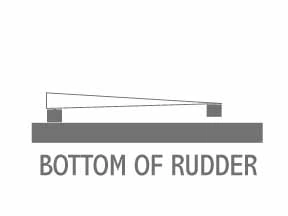
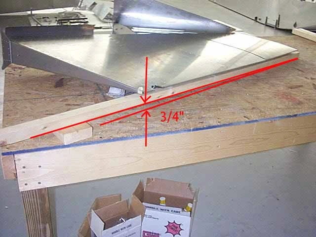
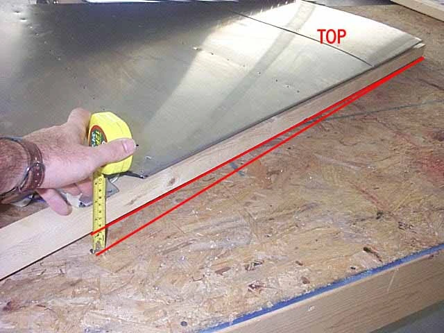
Смотрите чертёж 640-R-5. Руль направления сужается кверху, поэтому при укладке на плоский стол нижнюю часть задней кромки нужно приподнять.

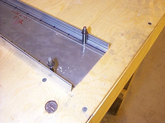
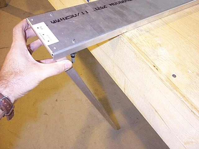
Положите два прямых деревянных бруска сечением 2×2 либо 2×4 дюйма: один под лонжерон, другой под заднюю кромку. Нижний конец задней кромки поднимите примерно на 3/4″, как на фотографиях. Без этого можно придать рулю крутку.

Важно: используйте опору 3/4″ КАЖДЫЙ раз, когда руль лежит плоско на верстаке, особенно при сверлении обшивок по каркасу. От этого зависит его симметрия.

Не сжимайте предформованную заднюю кромку обшивки: можно получить необратимый залом. Распределяйте прижимное усилие по большой площади.

Сверить с исходным текстом
POSITIONING THE RUDDER SKINS: See drawing 640-R-5 Since the rudder tail section tapers in width (the rudder is wider at the bottom and narrows at the top), it is important that when it lies flat on your workbench, the bottom trailing edge section of the rudder be raised to compensate. Take two straight 2×2 or 2×4 pieces of wood. Place one under the spar and the other under the trailing edge. Raise the bottom of the trailing edge up by about 3/4" as shown on the photo's. Failure to do so may force a "twist" in the rudder. Remember to use the 3/4" wedge each time you place the rudder flat on your workbench, especially when drilling the rudder skins to the skeleton assembly, as this determines how symmetrical your rudder will be. HANDLE THE PRE-FORMED SKINS WITH CARE . When working along the trailing edge of the pre-formed rear rudder skin, do not squeeze trailing edge, as this may force a permanent ‘kink’ in the material. If applying pressure, apply over large area so not to damage skin.

CH 640 · Руль направления · Раздел 9 из 12

Задние обшивки и сверление каркаса
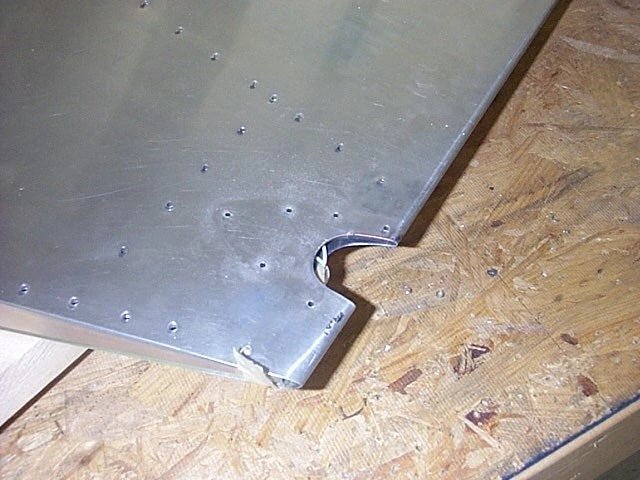
Подрежьте задние обшивки 20-R-5-2 и 20-R-5-1 по чертежам. В нижней обшивке вырежьте показанный треугольник снизу и два небольших выреза сверху.

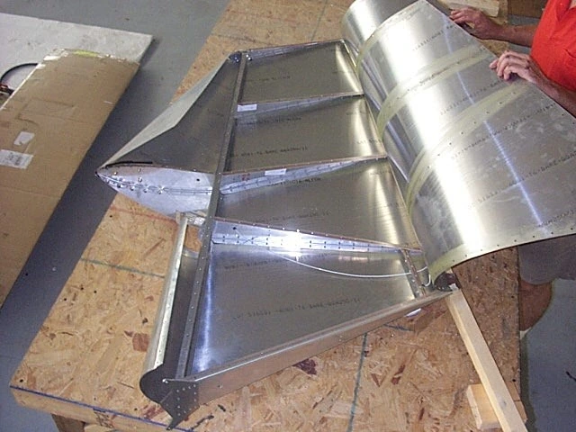
Уложите каркас в предформованные задние обшивки по 640-R-5, сначала работая с одной стороной. Верхняя и нижняя обшивки соединяются у нервюры 20-R-6-4. Верхняя перекрывает нижнюю примерно на 20mm; минимальный нахлёст 15mm необходим для отступа заклёпок от края. Верх верхней обшивки совместите с верхом концевой нервюры, низ нижней — с низом лонжерона. Проверьте общую подгонку.

Переносите сформованные обшивки, удерживая руками за радиус с обоих концов. Не допускайте вмятин и заломов.

Профиль 20-R-5-3 находится между двумя нижними нервюрами по чертежу 20-R-5. Его положение задаёт расстояние 125mm между нервюрами. Сверлите этот профиль после закрепления задней обшивки Cleco на нервюрах.

Обшивки местами специально поставляются с припуском и требуют подрезки ручными ножницами. Готовые отверстия задних обшивок задают положение нервюр; при необходимости подведите нервюры рукой к этим отверстиям.

Совместите низ задней обшивки с нижней кромкой лонжерона и 20-R-6-1. На обшивке проведите линию по середине уголка лонжерона. Разметьте отверстия с шагом 40mm, начиная снизу. Снимите обшивки и просверлите эти отверстия. Все отверстия обшивок в этом разделе — #30 под A4, шаг p.40.

Проведите оси на лонжероне и нервюрах. Снова установите обшивки, совместите отверстия с линиями, просверлите лонжерон через обшивку и закрепите Cleco. Затем совместите задние нервюры с отверстиями обшивки, просверлите и закрепите Cleco. Пока не снимайте временные крепления.

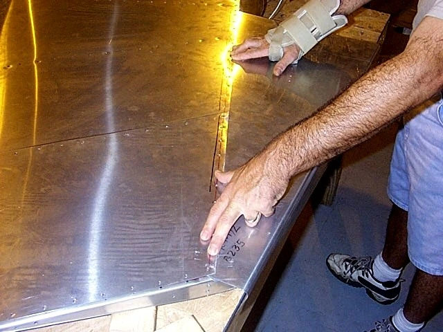
Переверните весь узел, отметьте оси нервюр и лонжерона на второй стороне. Через готовые отверстия обшивки сверлите нервюры, начиная от задней кромки и продвигаясь к лонжерону. Проверьте деревянные опоры и подъём нижнего конца задней кромки на 3/4″. Затем просверлите отверстия лонжерона, используя достаточно Cleco.

У задней кромки не нажимайте сильно и не просверлите противоположную сторону руля. Для концевой и нижней нервюр здесь не используют осевую линию полки: кромку обшивки располагают чуть ниже радиуса нервюры, чтобы получить аккуратное сопряжение. Удерживайте узел плоско на ровном верстаке.

Сверить с исходным текстом
Installing the two rear rudder skins (20-R-5-2 and 20-R-5-1) to the Rudder skeleton assembly. Cut the two rear skins as per the drawings. For the Lower Rear Skin, cut out the triangle at the bottom and two small ones at the top, as shown. Place the rudder skeleton assembly inside the pre-formed rear rudder skins (lay flat on workbench), as shown on Drawing 640-R-5, working on one side only. The Upper and Lower Rear Skins are joined together at rib 20-R-6-4 . The top skin overlaps the bottom skin by about 20mm. Minimum overlap is 15mm for minimum edge distance. The top of the top rear skin should be lined up with the top of the tip rib, and the bottom skin to the bottom of the spar. Make sure that everything fits properly. NOTICE : Handle skins with care — they are fragile and may dent with improper handling. Handle formed skins by the radius (placing hands inside radius at both ends, and lifting). Locate 20-R-5-3 as shown in drawing 20-R-5. This channel goes between the two bottom ribs. The actual location of this channel locates the distance between the two ribs so that there is 125 mm between them. Drill the channel after the rear skin is cleco'd to the ribs. NOTICE : The pre-formed skins are purposely supplied over-sized (when applicable), and may require trimming of edges with hand snips. The rear skins are pre-drilled for the ribs. The holes will give you the exact location of the ribs. You may have to move the ribs with your hands so that the ribs line up with the pre-drilled skins. Line up the bottom of the rear skin to the bottom of the spar and 20-R-6-1 Draw a marker line on top of the rear skins so that it is in the center of the spar angle. Mark a hole pitch of 40mm starting at the bottom. Remove the rear skins and drill the spar holes in the skins. All holes on the skins are #30 (A4 rivets) p. 40 Mark the center line on the spar and ribs. Re-install the rear skins and line up holes to the marker lines. Drill through the pre-drilled holes in the skins, into the spar. Now that the skins are cleco'd to the spar, line up the rear ribs to the skins and drill. Cleco as you drill. Do not remove the cleco's at this time. Turn the complete rudder assembly around and mark the center line of the ribs and spar. Through the pre-drilled holes, drill the holes in the ribs starting at the trailing edge and move towards the spar. Always make sure that the rudder is properly positioned on the wood blocks and that the bottom trailing edge is lifted by 3/4". Drill the spar holes. Remember to use lots of cleco's. Note: installing the rudder skins is probably the hardest area of the aircraft. Once you have mastered the rudder assembly, you will have an excellent understanding of basic sheet metal assembly. When drilling near the trailing edge, be careful not to press too hard (do not drill right into the other side of the rudder). For the TIP RIB and bottom rib, do not use a center line on the rib flange: Position the skin edge just inside (below) the rib radius for a nice finish. HINT : Keep material firmly flat on your workbench (which must be straight and level).

CH 640 · Руль направления · Раздел 10 из 12

Носовая обшивка и подготовка к окончательной клёпке
Оставьте задние обшивки закреплёнными Cleco, но выньте Cleco вдоль лонжерона. Для примерки вставьте носовую обшивку 20-R-1-1 между задними обшивками и лонжероном — так легче удержать её на месте. Можно плотно зафиксировать оба конца прочной упаковочной лентой с обеих сторон.

Передний радиус носовой обшивки должен совпадать с передними точками и центром носовых нервюр. Нижняя носовая нервюра 20-R-3-1 расположена под углом 90° к лонжерону.

Через готовые отверстия задних обшивок просверлите отверстия лонжерона, устанавливая Cleco. Переверните узел и повторите. Носовая обшивка должна плотно прилегать к носовым нервюрам. Просверлите отверстия в 20-R-3-1.

На полках носовой и концевой нервюр есть гофры, формирующие закругление. Не располагайте заклёпочные отверстия в зонах гофр. Для концевой нервюры наметьте одно отверстие за гофрированным участком; для носовой — шесть отверстий с шагом 40mm, обходя гофры.

Тем же способом установите обтекатель 20-R-5-4; смотрите сечение B-B листа 640-R-5. Носовая обшивка имеет припуск и может требовать подрезки, например у законцовки. Отметьте нужные места.

Проверьте, что просверлены все отверстия обшивок, включая крепление 20-R-5-3. Снимите обшивки с каркаса, очистите, подрежьте, проверьте размеры отверстий в нервюрах, лонжероне и обшивках, удалите заусенцы и при необходимости нанесите антикоррозионное покрытие.

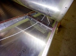
На этом этапе обязательно установите балансир 20-R-5-5 и надёжно закрепите его болтами на носовой нервюре. При выборе хвостового огня также сейчас проложите провод 16 AWG по 640-R-5. Вырез под огонь показан снизу у задней кромки; сам вырез и огонь можно выполнить и установить после завершения руля. Это опция.

Сверить с исходным текстом
Installing the Nose Skin (20-R-1-1) to the Rudder assembly Keeping the rear skins cleco'd in position, remove the cleco's at the spar. For positioning purposes, slide the Nose Skin in between the Rear Skins and the Spar, this is a helpful construction method to hold the Skin in place. SUGGESTION : You may find it easier to TAPE the skin in position, using a sturdy "shipping" or "duct" tape, taping both ends of the Nose Skin tightly to the Rear Skin, on both sides. NOTE: When positioning the Nose Skin make sure that the radius (leading edge) of the skin is positioned directly across the leading edge (most forward) part of the ribs. Make sure that the nose skin front radius is centered with the center of the nose ribs. Note that the bottom nose rib, 20-R-3-1, is angled 90 degrees to the spar. Once in position, drill the spar holes, through the pre-drilled holes in the rear skins. Cleco as you drill. Turn the assembly around and repeat the above instructions. Nose skin should be tight against the nose ribs. Drill holes in 20-R-3-1 nose rib. Notice that the Nose Rib and Tip Rib have been crimped (a crimp is placed on the flange to form the round edge of a rib — the crimp takes up the excess material in the forming process). When positioning the rivet holes it is important to avoid an area that has been crimped. Mark a single hole for the Tip Rib on the skin, just beyond the crimped area on the Tip Rib, and mark 6 holes on the skin for the Nose Rib (pitch 40, avoiding crimped areas). Install 20-R-5-4 fairing using same procedure as above. See drawing 640-R-5 section B-B for installation. Note that the pre-formed Nose Skin is supplied slightly oversized, and may require some trimming to provide a nice finish. Mark where trimming is required such as the tip area. Now inspect your rudder and make sure that all skin holes are drilled, including 20-R-5-3. Take the skins off the "skeleton" assembly (remove clecos) , clean them, trim them, inspect the hole tolerances in the ribs spar and skins, deburr and corrosion protect. Make sure that the Balance Mass 20-R-5-5 is installed at this time and properly bolted to the nose rib. Install wire for tail light at this time (optional — see 640-R-5, 16 awg. wire). Photo shows cut-out at rear bottom trailing edge for tail light (option). This may be cut-out and installed once the rudder is finished.

CH 640 · Руль направления · Раздел 11 из 12

Клёпка обшивок и кабанчик

Снова соберите обшивки на Cleco и приклепайте к каркасу. Если заклёпка не входит из-за небольшого несовпадения отверстий, осторожно совместите их проходом сверла в пределах заданного размера.

Установите кабанчик 20-R-7-1. Сначала проверьте его форму по чертежам и просверлите отверстия в кабанчике. Затем выставьте его на нижней задней нервюре по чертежу 20-R-7. Здесь применяются более крупные заклёпки A5; устанавливайте их со стороны кабанчика в нервюру.

Важно: положение кабанчика принципиально важно. По 640-R-7 расстояние от передней стороны лонжерона до направляющего отверстия 1/8″ составляет 11mm; при окончательном рассверливании отверстие увеличивается до 5/16″. Сохраняйте именно эту привязку по чертежу.

Сверить с исходным текстом
Riveting the Skins to the Rudder Assembly You've now completed all the hard work! Now, all you need to do to complete the rudder is to rivet the skins in place. Cleco the skin parts back together again, and rivet together. If you find that the holes don't match up together exactly (the rivet may not want to fit in the hole) — if this happens, simply re-drill the holes lightly. You can now install the Rudder Horn 20-R-7-1. Before installing, make sure that the shape is as per drawings. Drill the holes in the Rudder Horn first. Now position the Horn to the lower Rear Rib as per drawing 20-R-7. Note that the rivet size is larger. Use the A5 rivets and rivet from the horn into The rib. The location of the Horn is critical. Drawing 640-R-7 shows 11mm from the front of the spar to the 1/8 pilot hole (5/16 when open). Congratulations ! You've now completed the rudder tail section, which is a significant section of your own aircraft!

CH 640 · Руль направления · Раздел 12 из 12

Перечень деталей

640-R-2-5 — лонжерон, 1; 640-R-2-6 — усилитель лонжерона, 2.

640-R-6-1 — нижняя задняя нервюра, 1; 640-R-6-2 — задняя нервюра, 1; 640-R-6-3 — задняя нервюра, 1; 640-R-6-4 — задняя нервюра, 1.

640-R-5-3 — соединительный профиль, 1; 640-R-3-1 — носовая нервюра, 1; 640-R-3-2 — концевая нервюра, 1.

Стандартный L-образный уголок длиной 35mm, раскрытый на 18°, — 1. 640-R-4-2 — верхний кронштейн навески, 2.

640-R-5-2 — нижняя задняя обшивка, 1; 640-R-5-1 — верхняя задняя обшивка, 1; 640-R-1-1 — носовая обшивка, 1.

640-R-5-5 — балансир с защитным покрытием, 1. В перечне указан диапазон массы балансира от 1.25kg до 1.35kg. Сверяйте требования с применимой редакцией чертежей.

640-R-5-4 — обтекатель, 1; 640-R-7-1 — кабанчик руля направления, 1.

Заклёпки по ведомости: A5 — 22 штуки; A4 — 275 штук.

Сверить с исходным текстом
Required parts PART NO DESCRIPTION QUANTITY 640-R-2-5 SPAR 1 640-R-2-6 SPAR DOUBLER 2 640-R-6-1 LOWER REAR RIB 1 640-R-6-2 REAR RIB 1 640-R-6-3 REAR RIB 1 640-R-6-4 REAR RIB 1 640-R-5-3 CHANNEL 1 640-R-3-1 NOSE RIB 1 640-R-3-2 TIP RIB 1 L STANDARD Lx35mm OPENED 18 degrees 1 640-R-4-2 UPPER HINGE BRACKET 2 640-R-5-2 REAR SKIN LOWER 1 640-R-5-1 REAR SKIN UPPER 1 640-R-5-5 COATED BALANCE MASS. 1 WEIGHT OF BALANCE MASS MUST BE 1.25KG TO 1.35KG 1 640-R-1-1 NOSE SKIN 1 640-R-5-4 FAIRING 1 640-R-7-1 RUDDER HORN 1 A5 A5 RIVET 22 A4 A4 RIVETS 275 -END-

Корзина

0
image/svg+xml

No products in the cart.

Continue Shopping