CH 750 Cruzer · Управление рулём направления · Страница 1 из 9
Управление рулём направления: применимость
Раздел C75-CA-3 описывает педальное управление Cruzer. Фотографии дополняют чертежи; при расхождениях действуют применимые чертежи. Допуски — по Construction Standards for Zenair Light Aircraft.
Сверить с исходным текстом
CRUZER
Zenith Aircraft Company
Rudder Controls
Section C75-CA-3, Page 1 of 9
Revision 1.0 (12/21/2015)
Section C75-CA-3
Rudder Controls
This manual has been prepared for assembly of the Rudder Controls. This photo assembly manual is
intended as a supplement to the drawings. If there is any discrepancy between this manual and the
drawings, the drawings supersede this manual. For more information on building standards and allowable
tolerances see “Construction Standards for Zenair Light Aircraft” available from Zenith Aircraft Co.
CH 750 Cruzer · Управление рулём направления · Страница 2 из 9
Опоры педалей
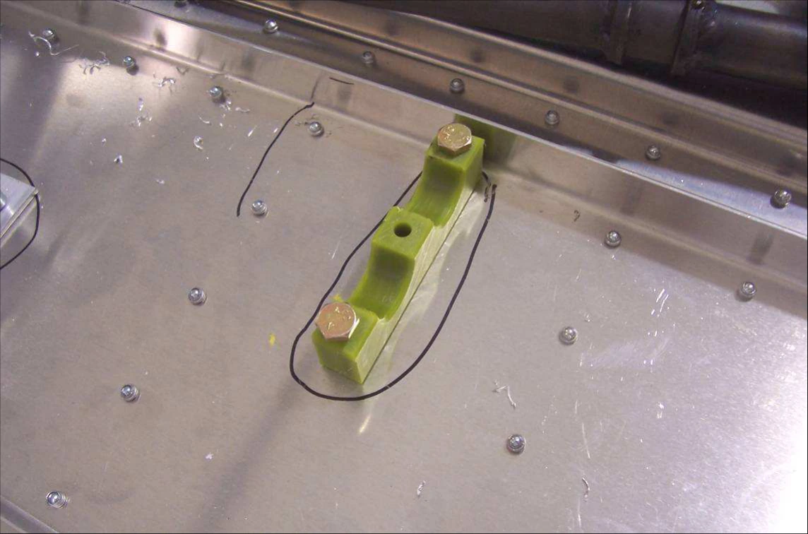
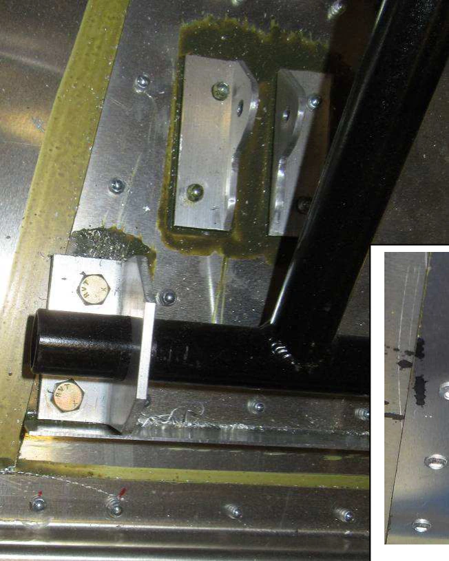
Рассверлите отверстия в профиле опор педалей и полу кабины сверлом #12. Установите нижнюю половину центрального подшипника C75C3-5 на профиль. Наденьте боковой подшипник C75C3-6 на конец педали C75C3-3.
Сверить с исходным текстом
CRUZER
Zenith Aircraft Company
Rudder Controls
Section C75-CA-3, Page 2 of 9
Revision 1.0 (12/21/2015)
Use a #12 drill bit to open the holes in the Pedal Bearing Channel and Cabin Floor.
Set the lower half of the Central Bearing in place on the Bearing Channel.
P/N: C75C3-5
Central Pedal
Bearing
P/N: C75C3-3
Rudder Pedal
P/N: C75C3-6
Lateral Pedal Bearing
Slide the Lateral
Pedal Bearing on the
end of the Rudder
Pedal
CH 750 Cruzer · Управление рулём направления · Страница 3 из 9
Ориентация педалей
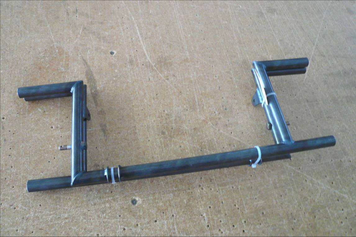
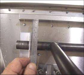
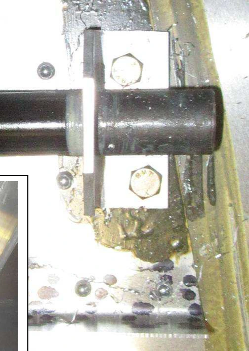
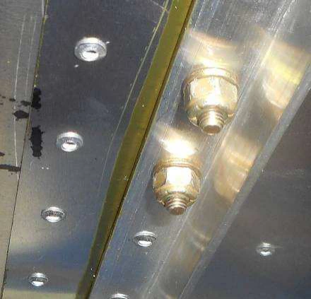
Педали расположены перпендикулярно продольной оси самолёта, параллельно сторонам профиля опор. Ушки тросов направлены назад. Болты проходят посередине экструдированного профиля C75F13-1 под фюзеляжем.
Сверить с исходным текстом
CRUZER
Zenith Aircraft Company
Rudder Controls
Section C75-CA-3, Page 3 of 9
Revision 1.0 (12/21/2015)
The rudder pedals are square to the aircraft center line (parallel to the sides of the channel)
NOTE: The tabs for the rudder cables point towards the rear.
Locate the bolts in the middle of the
Extrusion C75F13-1
underneath the fuselage
CH 750 Cruzer · Управление рулём направления · Страница 4 из 9
Петли тормозных педалей
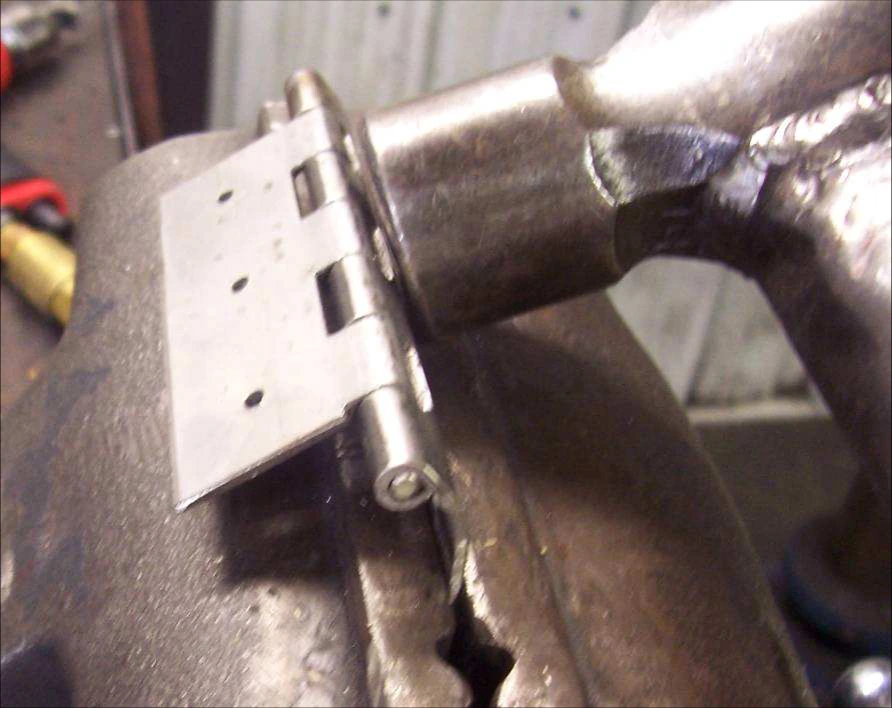
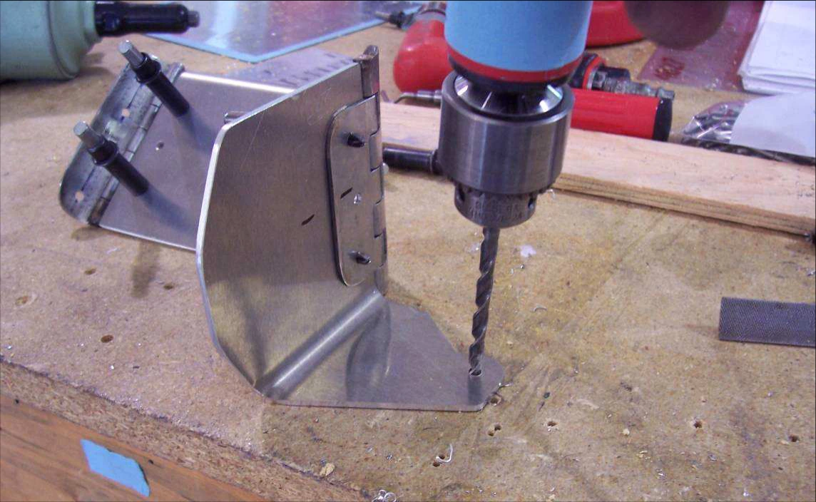
В тисках молотком постепенно изогните длинную полку нержавеющей рояльной петли C75C3-4 по форме педали. Делайте несколько небольших изгибов для плавной кривизны; полка выгибается в сторону цилиндрической части петли.
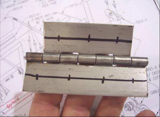
Проведите осевые линии обеих полок. На длинной разметьте четыре заклёпки, на короткой — три. Крайние отверстия расположены в 10mm от концов. Сверлите #40.
Сверить с исходным текстом
CRUZER
Zenith Aircraft Company
Rudder Controls
Section C75-CA-3, Page 4 of 9
Revision 1.0 (12/21/2015)
Use a vise and hammer to curve the longer flange to match the curve of the Pedals. Make small bends in
several locations to form a smooth curve. The flange should be curved on the side with the barrel.
P/N: C75C3-4
S.S. Piano Hinge
Draw center lines on both flanges of the
S.S. Piano Hinge. Layout four rivet
locations on the longer flange and three
on the shorter flange. The end rivets
should be 10mm from each end.
Use a #40 drill bit to drill the rivet holes.
CH 750 Cruzer · Управление рулём направления · Страница 5 из 9
Петля на тормозной педали
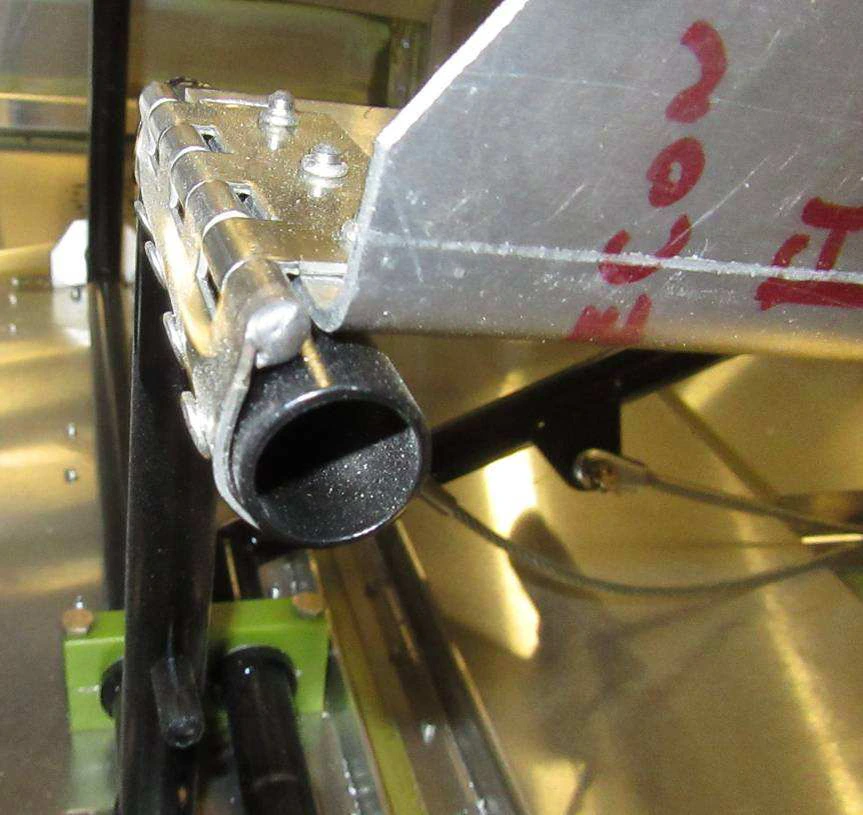
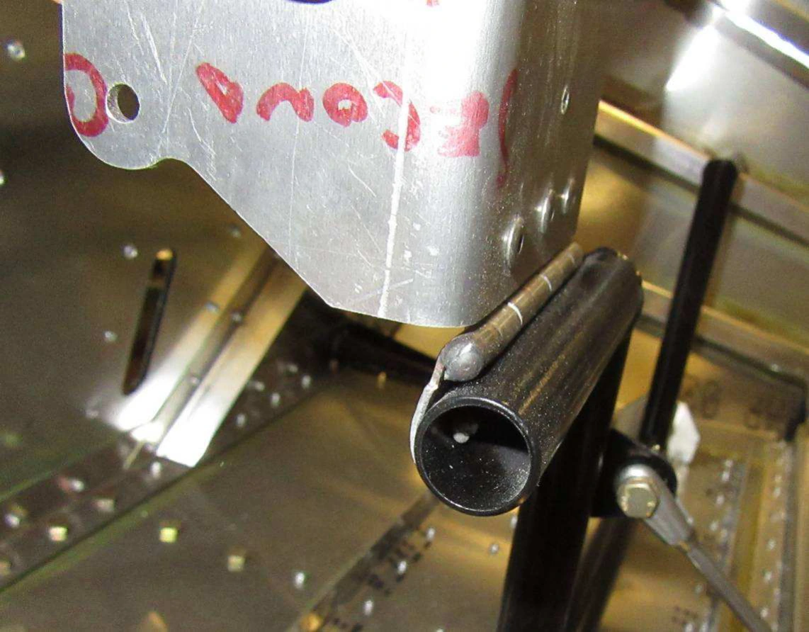
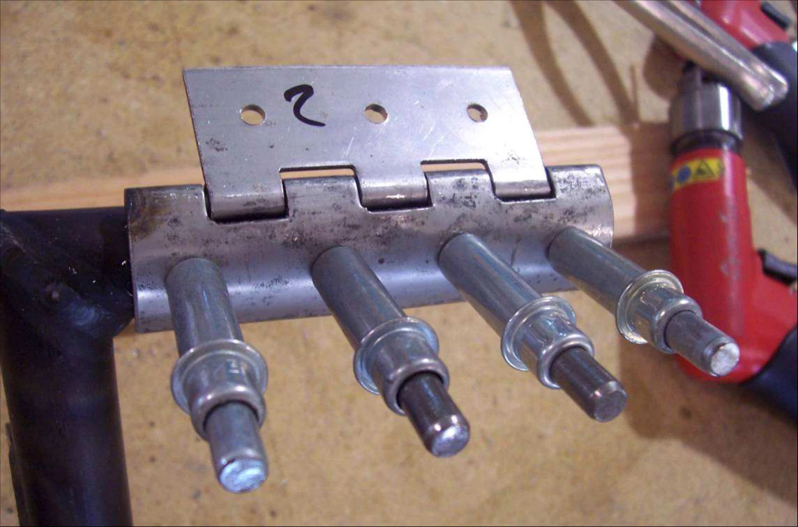
Отцентрируйте петлю на тормозной педали C75C3-9; цилиндрическая часть прилегает к её низу, изогнутая полка направлена вперёд. Сверлите педаль через петлю #40 с Cleco, затем рассверлите #20. Отверстие тормозного цилиндра увеличьте #12.
Сверить с исходным текстом
CRUZER
Zenith Aircraft Company
Rudder Controls
Section C75-CA-3, Page 5 of 9
Revision 1.0 (12/21/2015)
Position the Hinge on the Toe Brake Pedal. Center the Hinge on the Toe Brake and
the barrel of the Hinge against the bottom of the Toe Brake. Make sure the curved
flange is towards the front of the Toe Brake. With a #40 drill bit, back drill through the
Hinge into the Toe Brake and cleco. Expand the holes with a #20 drill bit.
P/N: C75C3-9
Toe Brake Pedal
Use a #12 drill bit to expand the hole for the Brake Cylinder.
CH 750 Cruzer · Управление рулём направления · Страница 6 из 9
Петля на педали направления
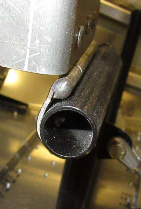
Конец длинной полки петли совместите с концом педали направления. Сверлите по петле в педаль #40 с Cleco, затем рассверлите #20.
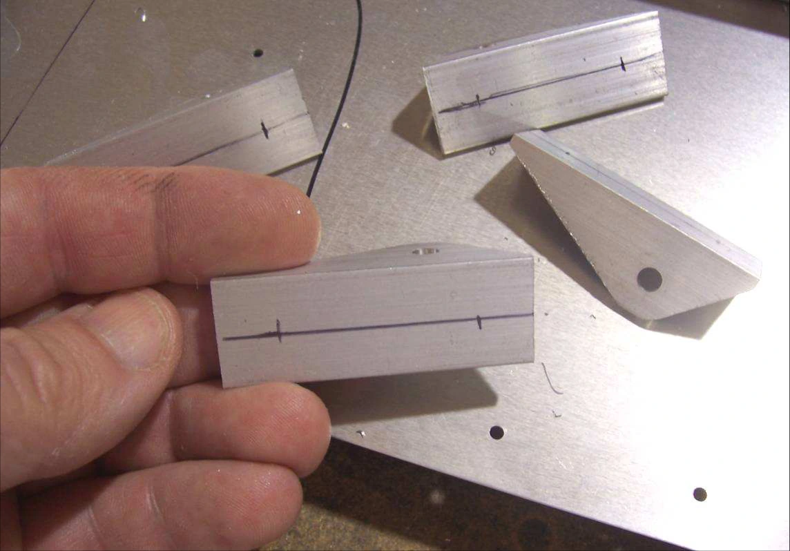
На нижней полке опор тормозного цилиндра C75C3-7 проведите осевую линию. Отметьте заклёпки в 10mm от каждого конца.
Сверить с исходным текстом
CRUZER
Zenith Aircraft Company
Rudder Controls
Section C75-CA-3, Page 6 of 9
Revision 1.0 (12/21/2015)
Set the Hinge on the Rudder Pedal. The end of the long flange should be flush with the end of the Pedal.
With a #40 drill bit, back drill through the Hinge into the Pedal and cleco. Expand the holes with a #20 drill
bit.
Draw a center line on the bottom flange of the Brake Cylinder Supports. Mark rivet
locations 10mm from each end of the Supports.
P/N: C75C3-7
Brake Cylinder
Support
CH 750 Cruzer · Управление рулём направления · Страница 7 из 9
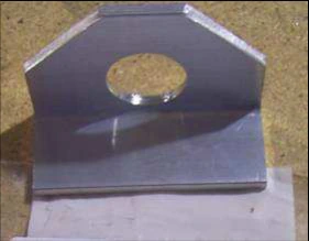
Опоры тормозного цилиндра
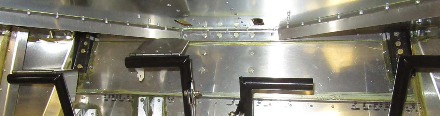
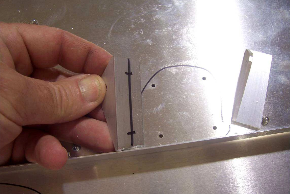
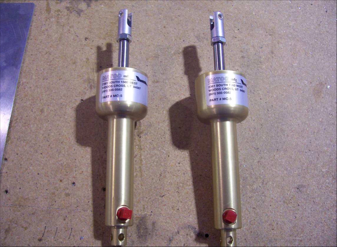
Расположите опоры на профиле педалей, совместив осевые линии с готовыми отверстиями. Сверлите опоры через профиль #40 с Cleco. Положение и ориентация — по C75-CA-3. На странице обозначен главный тормозной цилиндр MC-5.
Сверить с исходным текстом
CRUZER
Zenith Aircraft Company
Rudder Controls
Section C75-CA-3, Page 7 of 9
Revision 1.0 (12/21/2015)
Position the Supports on the Pedal Bearing Channel. With the lines visible through the predrilled holes back
drill through the Pedal Bearing Channel into the Supports with a #40 drill bit and cleco.
See drawing C75-CA-3 for position and orientation information.
P/N: MC-5
Brake Master
Cylinder
CH 750 Cruzer · Управление рулём направления · Страница 8 из 9
Тормозной цилиндр и тяги
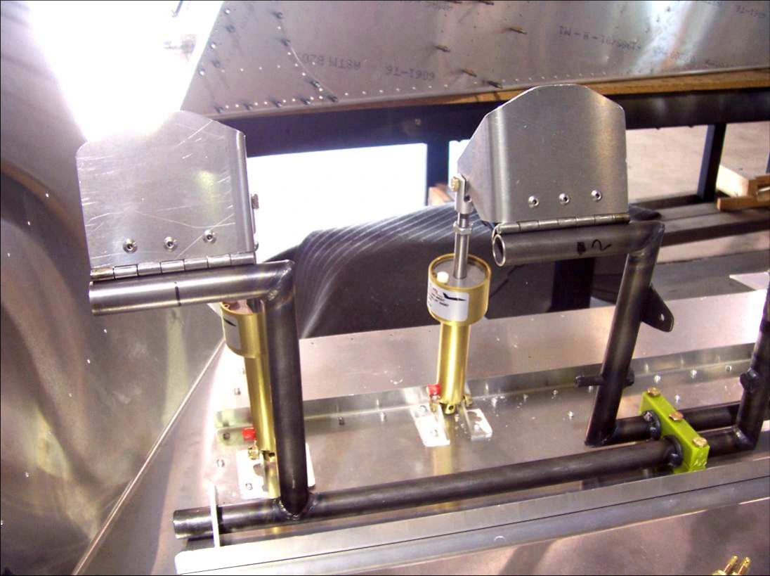
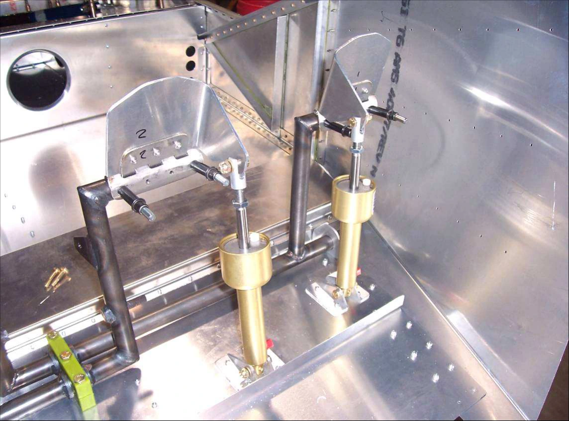
Монтажные отверстия опор цилиндра рассверлите #12. Закрепите цилиндр болтами на опорах и тормозных педалях. Наклон педали регулируется вилкой цилиндра, но регулировку отложите до установки тяг управления носовой стойкой.
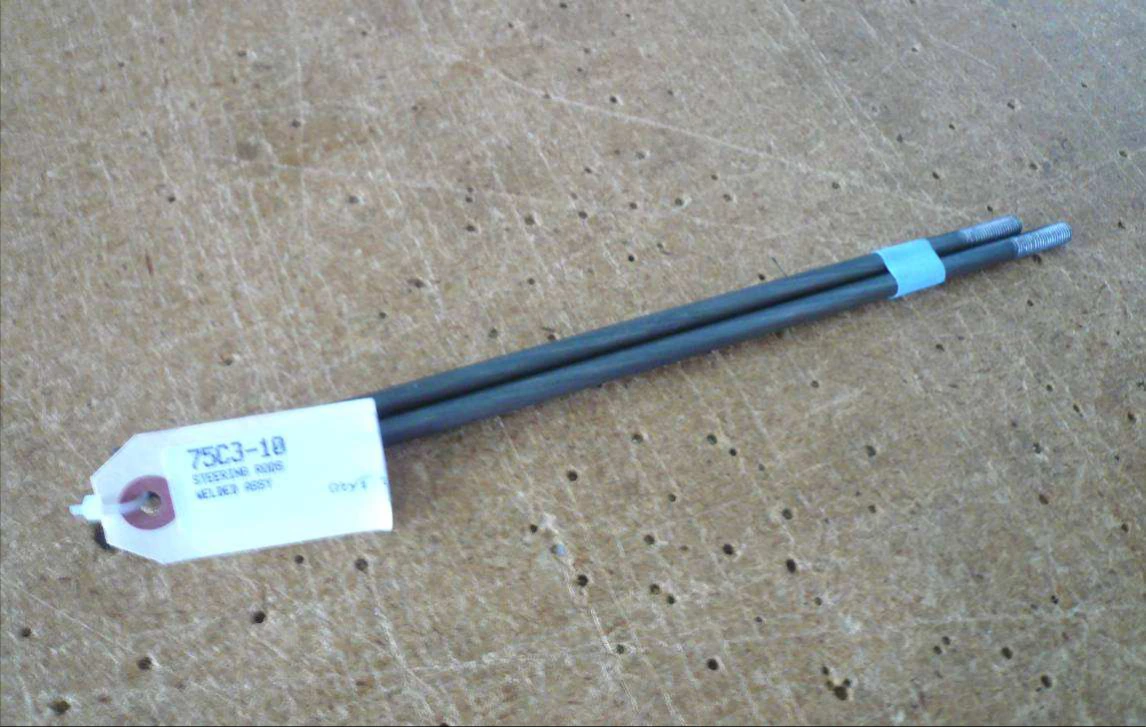
Примечание: подпись этой страницы называет тягу C75C3-9, тогда как на странице 5 тот же номер присвоен тормозной педали. Это противоречие источника; номер тяги уточните по применимому чертежу, не заказывайте её только по этой подписи.
Сверить с исходным текстом
CRUZER
Zenith Aircraft Company
Rudder Controls
Section C75-CA-3, Page 8 of 9
Revision 1.0 (12/21/2015)
Use a #12 drill bit to expand the mounting holes in the Brake Cylinder Supports. Bolt the Master Cylinder to
the Supports and the Toe Brake Pedals. The angle of the Toe Brake Pedal can be adjusted by loosening or
tightening the clevis on the Brake Master Cylinder but wait to do this until the Steering Rods are installed.
P/N: C75C3-9
Steering Rod
CH 750 Cruzer · Управление рулём направления · Страница 9 из 9
Установка тяг носовой стойки
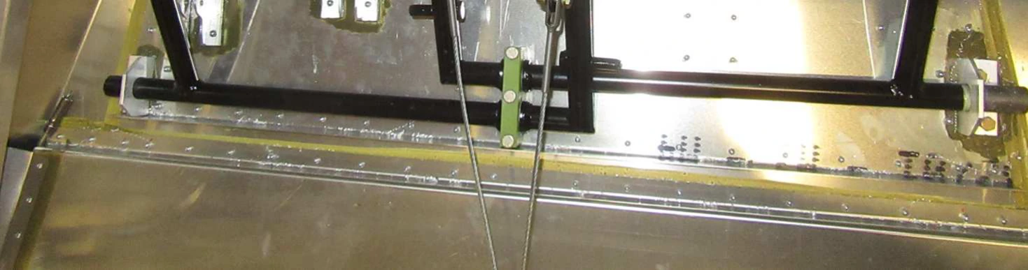
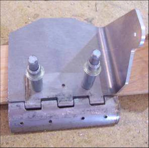
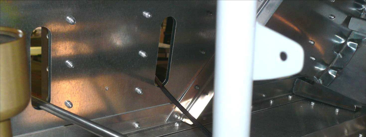
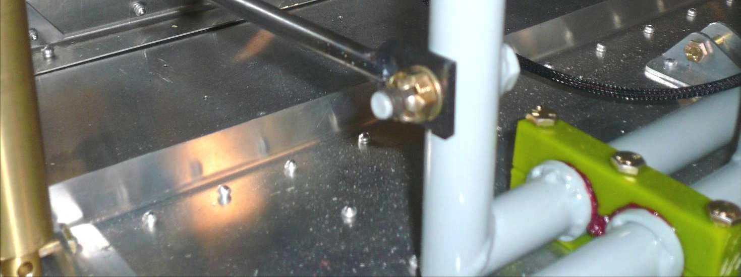
Установите тяги на педали с корончатыми гайками и шплинтами. По источнику гайки не затягиваются до зажима шарнира: тяги должны свободно поворачиваться на шпильках.
Левая тяга пилота короче правой пассажирской. Окончательную фиксацию и допустимый люфт сверяйте по чертежу соединения.
Сверить с исходным текстом
CRUZER
Zenith Aircraft Company
Rudder Controls
Section C75-CA-3, Page 9 of 9
Revision 1.0 (12/21/2015)
Install the Steering Rods on the Rudder Pedals using a castle nut and cotter pin. Don’t tighten the nut on the
Steering Rods; the Steering Rods should rotate freely on the stud.
Note: The pilot side (left) Steering Rod is shorter than the passenger (right) side.